ENGINE DISASSEMBLY/ASSEMBLY [SKYACTIV-G 2.0]
CAUTION:
When the transmission is installed, do not suspend the engine. Otherwise, the SST installation area of the cylinder head may be damaged due to excess weight. Only suspend the engine after separating the engine and transmission.
Applying excessive force (force of 100 N {10.2 kgf, 22.5 lbf} or more) to the electric variable valve timing motor/driver may cause a malfunction. When servicing, be careful not to apply excessive force to the electric variable valve timing motor/driver using other parts or tools.
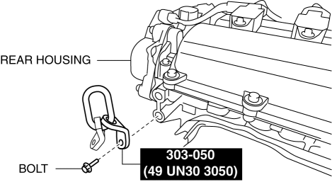
1. Install the SST and the following bolt to the position shown in the figure.Engine rear side
Bolt:
part number 99794 1025 or an M10 × 1.25, length 25 mm {0.98 in}
Tightening torque
38—52 N·m {3.9—5.3 kgf·m, 29—38 ft·lbf}
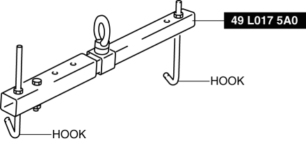
2. Engage the hooks of the SST (49 L017 5A0) to the SST (49 UN30 3050).
CAUTION:
Do not lift up the engine.
3. To ensure the safety of the work (control engine and transmission sway), set a hoist.
4. Remove the engine mount rubber and engine mount bracket. (See ENGINE MOUNT DISASSEMBLY/ASSEMBLY [SKYACTIV-G 2.0].)
5. Remove the exhaust system. (See EXHAUST SYSTEM REMOVAL/INSTALLATION [SKYACTIV-G 2.0].)
6. Remove the oil pipes and oil hoses. (AT) (See OIL COOLER REMOVAL/INSTALLATION [SJ6A-EL].)
7. Remove the starter. (See STARTER REMOVAL/INSTALLATION [SKYACTIV-G 2.0].)
8. Fix the drive plate using the crankshaft pulley lock bolt. (AT)
9. Remove the torque converter installation nut from the starter installation hole. (AT) (See AUTOMATIC TRANSMISSION REMOVAL/INSTALLATION [SJ6A-EL].)
10. Disconnect the engine and transmission, and lower only the engine from the engine lifter. (See TRANSMISSION REMOVAL/INSTALLATION [M66M-D] (MT).) (See AUTOMATIC TRANSMISSION REMOVAL/INSTALLATION [SJ6A-EL] (AT).)
11. Remove the intake-air system. (See INTAKE-AIR SYSTEM REMOVAL/INSTALLATION [SKYACTIV-G 2.0].)
12. Remove the oil separator. (See POSITIVE CRANKCASE VENTILATION (PCV) VALVE REMOVAL/INSTALLATION [SKYACTIV-G 2.0].)
13. Remove the knock sensor (KS). (See KNOCK SENSOR (KS) REMOVAL/INSTALLATION [SKYACTIV-G 2.0].)
14. Remove the fuel injectors. (See FUEL INJECTOR REMOVAL/INSTALLATION [SKYACTIV-G 2.0].)
15. Remove the camshaft position (CMP) sensor. (See CAMSHAFT POSITION (CMP) SENSOR REMOVAL/INSTALLATION [SKYACTIV-G 2.0].)
16. Remove the high pressure fuel pump. (See HIGH PRESSURE FUEL PUMP REMOVAL/INSTALLATION [SKYACTIV-G 2.0].)
17. Remove the electric variable valve timing motor/driver. (See ELECTRIC VARIABLE VALVE TIMING MOTOR/DRIVER REMOVAL/INSTALLATION [SKYACTIV-G 2.0].)
18. Remove the water outlet component. (See TIMING CHAIN REMOVAL/INSTALLATION [SKYACTIV-G 2.0].)
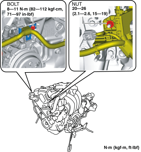
19. Remove the bolt and nut shown in the figure.
20. Remove the drive belt auto tensioner. (See DRIVE BELT AUTO TENSIONER REMOVAL/INSTALLATION [SKYACTIV-G 2.0].)
21. Remove the generator. (See GENERATOR REMOVAL/INSTALLATION [SKYACTIV-G 2.0].)
22. Remove the oil filter. (See OIL FILTER REPLACEMENT [SKYACTIV-G 2.0].)
23. Remove the engine oil solenoid valve. (See ENGINE OIL SOLENOID VALVE REMOVAL/INSTALLATION [SKYACTIV-G 2.0].)
24. Remove the crankshaft position (CKP) sensor. (See CRANKSHAFT POSITION (CKP) SENSOR REMOVAL/INSTALLATION [SKYACTIV-G 2.0].)
25. Remove the dipstick.
26. Remove the seal cover. (See SEAL COVER REMOVAL/INSTALLATION [SKYACTIV-G 2.0].)
27. Remove the ignition coil/ion sensors. (See IGNITION COIL/ION SENSOR REMOVAL/INSTALLATION [SKYACTIV-G 2.0].)
28. Remove the emission harness.
29. Remove the water pump drive belt. (See DRIVE BELT REMOVAL/INSTALLATION [SKYACTIV-G 2.0].)
30. Remove the water pump housing and water pump body. (See WATER PUMP REMOVAL/INSTALLATION [SKYACTIV-G 2.0].)
31. Remove the clutch cover and clutch disc. (MT) (See CLUTCH UNIT REMOVAL/INSTALLATION.)
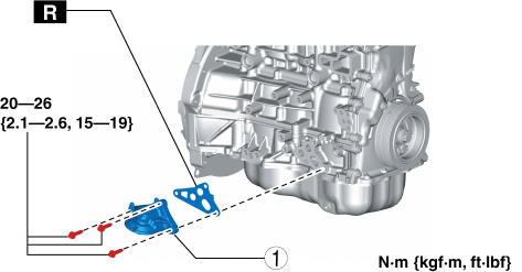
32. Remove in the order indicated in the table.
33. Assemble in the reverse order of disassembly.
| 1 |
Oil filter body |
Oil Filter Body Installation Note
NOTE:
The tightening order of the three bolts is optional.
1. After tightening the three bolts, tighten the first tightened bolt to the specified tightening torque again.< Previous Next >Tightening torque
20—26 N·m {2.1—2.6 kgf·m, 15—19 ft·lbf}


