MX5 mk4 Manual
Home bodyshop manual wiring diagram workshop manual service highlights transmission overhaul

Knowledge Base

Free to use workshop manual for your 2015+ Mk4 'ND' Mazda MX-5
Home


< Previous   Next >

DTC U2010:11 [ELECTRICAL SUPPLY UNIT (ESU)]

Description

Illumination output circuit malfunction

Detection condition

  • Electrical supply unit (ESU) detects a short to ground in the illumination output circuit.

Fail-safe

Not applicable

Possible cause

  • Electrical supply unit (ESU) connector or terminal malfunction

  • Illuminations malfunction

  • Short to ground in electrical supply unit (ESU) illumination output circuit

  • Electrical supply unit (ESU) malfunction

Diagnostic Procedure

Step

Inspection

Action

1

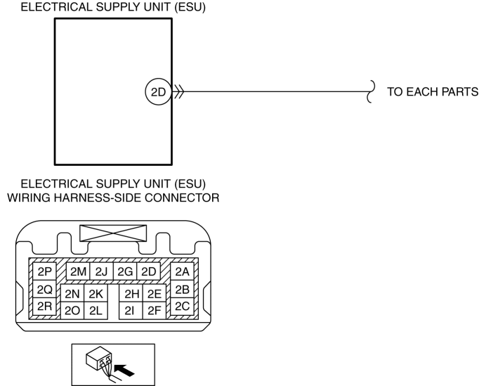
INSPECT ELECTRICAL SUPPLY UNIT (ESU) CONNECTOR CONDITION
  • Switch the ignition off.

  • Disconnect the negative battery cable.

    (See NEGATIVE BATTERY CABLE DISCONNECTION/CONNECTION.)

  • Disconnect the electrical supply unit (ESU) connector.

  • Inspect the connector engagement and connection condition and inspect the terminals for damage, deformation, corrosion, or disconnection.

  • Is the connector normal?

Yes

Go to the next step.

No

Repair or replace the connector, then go to Step 4.

2

INSPECT ILLUMINATION OUTPUT CIRCUIT FOR SHORT TO GROUND
  • Verify that the electrical supply unit (ESU) connector is disconnected.

  • Turn the light switch to the TNS (parking lights) position.

  • Inspect for continuity between electrical supply unit (ESU) terminal 2D (wiring harness-side) and body ground.

  • Is there continuity?

Yes

Go to the next step.

No

Go to Step 4.

3

INSPECT ILLUMINATIONS
  • Inspect the following parts:

    • Cruise control switch (With cruise control switch)

      (See CRUISE CONTROL SWITCH INSPECTION [SKYACTIV-G 2.0].)

    • Drive selection switch

      (See DRIVE SELECTION SWITCH INSPECTION [SKYACTIV-G 2.0].)

    • Trunk lid opener switch (interior)

      (See TRUNK LID OPENER SWITCH INSPECTION.)

    • Hazard warning switch

      (See HAZARD WARNING SWITCH INSPECTION.)

    • Steering switch

      (See STEERING SWITCH INSPECTION.)

    • Cluster switch

      (See DSC OFF SWITCH INSPECTION.)

      (See BLIND SPOT MONITORING (BSM) SWITCH INSPECTION.)

      (See LDWS SWITCH INSPECTION.)

  • Are all parts normal?

Yes

Refer to the wiring diagram and verify whether or not there is a common connector between the following terminals:

  • Cruise control switch???Electrical supply unit (ESU) terminal 2D (With cruise control switch)

  • Shift panel (indicator)???Electrical supply unit (ESU) terminal 2D (AT)

  • Drive selection switch???Electrical supply unit (ESU) terminal 2D

  • Trunk lid opener switch (interior)???Electrical supply unit (ESU) terminal 2D

  • Hazard warning switch???Electrical supply unit (ESU) terminal 2D

  • Audio unit???Electrical supply unit (ESU) terminal 2D (Without center display)

  • Commander switch???Electrical supply unit (ESU) terminal 2D (With center display)

  • CD player???Electrical supply unit (ESU) terminal 2D

  • Steering switch???Electrical supply unit (ESU) terminal 2D

  • Cluster switch???Electrical supply unit (ESU) terminal 2D

    If there is a common connector:
  • Determine the malfunctioning part by inspecting the common connector and the terminal for corrosion, damage, or pin disconnection, and the common wiring harness for a short to ground.

  • Repair or replace the malfunctioning part.

    If there is no common connector:
  • Repair or replace the wiring harness which has a short to ground.

Go to the next step.

No

Repair or replace the malfunctioning part, then go to the next step.

(See CRUISE CONTROL SWITCH REMOVAL/INSTALLATION [SKYACTIV-G 2.0].)

(See STEERING SWITCH REMOVAL/INSTALLATION.)

(See DRIVE SELECTION SWITCH REMOVAL/INSTALLATION [SKYACTIV-G 2.0].)

(See TRUNK LID OPENER SWITCH REMOVAL/INSTALLATION.)

(See HAZARD WARNING SWITCH REMOVAL/INSTALLATION.)

(See CLUSTER SWITCH REMOVAL/INSTALLATION.)

4

VERIFY THAT REPAIRS HAVE BEEN COMPLETED
  • Always reconnect all disconnected connectors.

  • Connect the negative battery cable.

    (See NEGATIVE BATTERY CABLE DISCONNECTION/CONNECTION.)

  • Clear the DTC for the electrical supply unit (ESU) using the M-MDS.

    (See CLEARING DTC [ELECTRICAL SUPPLY UNIT (ESU)].)

  • Turn the light switch to the TNS (parking lights) position.

  • Retrieve the electrical supply unit (ESU) DTCs using the M-MDS.

    (See DTC INSPECTION [ELECTRICAL SUPPLY UNIT (ESU)].)

  • Is the same DTC displayed?

Yes

Repeat the inspection from Step 1.

  • If the malfunction recurs, replace the electrical supply unit (ESU).

    (See ELECTRICAL SUPPLY UNIT (ESU) REMOVAL/INSTALLATION.)

Go to the next step.

No

Go to the next step.

5

VERIFY IF OTHER DTCs DISPLAYED
  • Are any other DTCs displayed?

Yes

Repair or replace the malfunctioning part according to the applicable DTC troubleshooting.

(See DTC TABLE [ELECTRICAL SUPPLY UNIT (ESU)].)

No

DTC troubleshooting completed.

< Previous   Next >
 

Free to use workshop manual for your 2015+ Mk4 'ND' Mazda MX-5

COPYRIGHT NOTICE:
This fan site is not affiliated with Mazda, and is intended for personal, or commercial use only. The content of our web pages is for general information purposes only and is presented “as is”. We give no assurance or warranty regarding the accuracy of the contents. Readers should do their due diligence and seek the advice of an appropriately certified automotive technician before attempting any steps on this site. Original content provided by Mazda North America. The content of the manual is copyright under DMCA to: full.metal.resistor@gmail.com
LIMITATION OF LIABILITY:
We accept no responsibility for errors, inaccuracies, or omissions found on these pages. Additionally, we hereby exclude liability for any demands, claims, damages or losses of any kind with regard to any content or information provided on our web-site, including but not limited to incidental or consequential damages, direct or indirect loss, compensatory damages, loss of profits, or otherwise. By using this manual you assume full liablity for any procedures carried out on your vehicle, and are responsible for the vehicle remaining road legal and safe.
Site design © MX5 Docs 2019
Privacy policy
Cookies
X
We use cookies to improve your experience on
our site. By using our site you consent to cookies.
Learn more
I Agree