MX5 mk4 Manual
Home bodyshop manual wiring diagram workshop manual service highlights transmission overhaul

Knowledge Base

Free to use workshop manual for your 2015+ Mk4 'ND' Mazda MX-5
Home


< Previous   Next >

DTC P1708:24 [START STOP UNIT]

Description

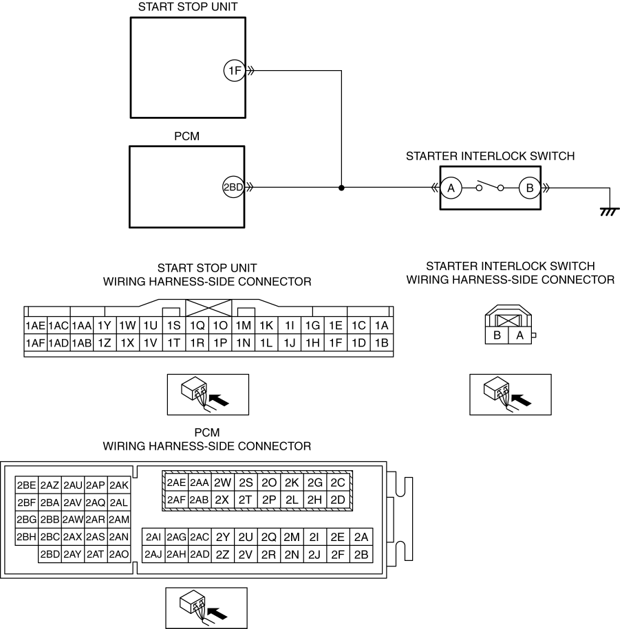
Starter interlock switch circuit malfunction

Detection condition

  • Start stop unit detects an open circuit in the starter interlock switch circuit for 0.5 s or more for a continuous 5 times with the ignition switched ON (engine off or on).

Fail-safe

  • Change to the back-up mode.

Possible cause

  • Starter interlock switch connector or terminal malfunction

  • Open circuit in wiring harness between starter interlock switch terminal B and body ground

  • Starter interlock switch malfunction

  • PCM connector or terminal malfunction

  • Start stop unit connector or terminal malfunction

  • Open circuit in wiring harness between the following terminals:

    • PCM terminal 2BD—Starter interlock switch terminal A

    • Start stop unit terminal 1F—Starter interlock switch terminal A

  • PCM malfunction

  • Start stop unit malfunction

Diagnostic Procedure

Step

Inspection

Action

1

INSPECT STARTER INTERLOCK SWITCH CONNECTOR CONDITION
  • Switch the ignition off.

  • Disconnect the negative battery cable.

    (See NEGATIVE BATTERY CABLE DISCONNECTION/CONNECTION.)

  • Disconnect the starter interlock switch connector.

  • Inspect the connector engagement and connection condition and inspect the terminals for damage, deformation, corrosion, or disconnection.

  • Is the connector normal?

Yes

Go to the next step.

No

Repair or replace the connector, then go to Step 8.

2

INSPECT STARTER INTERLOCK SWITCH GROUND CIRCUIT FOR OPEN CIRCUIT
  • Verify that the starter interlock switch connector is disconnected.

  • Inspect for continuity between starter interlock switch terminal B (wiring harness-side) and body ground.

  • Is there continuity?

Yes

Go to the next step.

No

Refer to the wiring diagram and verify whether or not there is a common connector between starter interlock switch terminal B and body ground.

    If there is a common connector:
  • Determine the malfunctioning part by inspecting the common connector and the terminal for corrosion, damage, or pin disconnection, and the common wiring harness for an open circuit.

  • Repair or replace the malfunctioning part.

    If there is no common connector:
  • Repair or replace the wiring harness which has an open circuit.

Go to Step 8.

3

INSPECT STARTER INTERLOCK SWITCH
  • Inspect the starter interlock switch.

    (See STARTER INTERLOCK SWITCH INSPECTION [SKYACTIV-G 2.0].)

  • Is the starter interlock switch normal?

Yes

Go to the next step.

No

Replace the starter interlock switch, then go to Step 8.

(See STARTER INTERLOCK SWITCH REMOVAL/INSTALLATION.)

4

INSPECT PCM CONNECTOR CONDITION
  • Disconnect the PCM connector.

  • Inspect the connector engagement and connection condition and inspect the terminals for damage, deformation, corrosion, or disconnection.

  • Is the connector normal?

Yes

Go to the next step.

No

Repair or replace the connector, then go to Step 8.

5

INSPECT START STOP UNIT CONNECTOR CONDITION
  • Disconnect the start stop unit connector.

  • Inspect the connector engagement and connection condition and inspect the terminals for damage, deformation, corrosion, or disconnection.

  • Is the connector normal?

Yes

Go to the next step.

No

Repair or replace the connector, then go to Step 8.

6

INSPECT STARTER INTERLOCK SWITCH CIRCUIT FOR OPEN CIRCUIT
  • Verify that the start stop unit, PCM and starter interlock switch connectors are disconnected.

  • Inspect for continuity between the following terminals (wiring harness-side):

    • PCM terminal 2BD—Starter interlock switch terminal A

    • Start stop unit terminal 1F—Starter interlock switch terminal A

  • Is there continuity?

Yes

Go to the next step.

No

Refer to the wiring diagram and verify whether or not there is a common connector between the following terminals:

  • PCM terminal 2BD—Starter interlock switch terminal A

  • Start stop unit terminal 1F—Starter interlock switch terminal A

    If there is a common connector:
  • Determine the malfunctioning part by inspecting the common connector and the terminal for corrosion, damage, or pin disconnection, and the common wiring harness for an open circuit.

  • Repair or replace the malfunctioning part.

    If there is no common connector:
  • Repair or replace the wiring harness which has an open circuit.

Go to Step 8.

7

VERIFY IF MALFUNCTIONING LOCATION IS PCM DEPENDING ON REPEATABILITY
  • Always reconnect all disconnected connectors.

  • Connect the negative battery cable.

    (See NEGATIVE BATTERY CABLE DISCONNECTION/CONNECTION.)

  • Clear the DTC for the start stop unit using the M-MDS.

    (See CLEARING DTC [START STOP UNIT].)

  • Switch the ignition ON (engine off or on).

  • Perform the following work 5 times or more.

    • Depress the clutch pedal for 1 s or more.

    • Release the clutch pedal for 1 s or more.

  • Retrieve the start stop unit DTCs using the M-MDS.

    (See DTC INSPECTION [START STOP UNIT].)

  • Is the same DTC displayed?

Yes

Replace the PCM, then go to the next step.

(See PCM REMOVAL/INSTALLATION [SKYACTIV-G 2.0].)

No

Go to Step 9.

8

VERIFY THAT REPAIRS HAVE BEEN COMPLETED
  • Always reconnect all disconnected connectors.

  • Connect the negative battery cable.

    (See NEGATIVE BATTERY CABLE DISCONNECTION/CONNECTION.)

  • Clear the DTC for the start stop unit using the M-MDS.

    (See CLEARING DTC [START STOP UNIT].)

  • Switch the ignition ON (engine off or on).

  • Perform the following work 5 times or more.

    • Depress the clutch pedal for 1 s or more.

    • Release the clutch pedal for 1 s or more.

  • Retrieve the start stop unit DTCs using the M-MDS.

    (See DTC INSPECTION [START STOP UNIT].)

  • Is the same DTC displayed?

Yes

Repeat the inspection from Step 1.

  • If the malfunction recurs, replace the start stop unit.

    (See START STOP UNIT REMOVAL/INSTALLATION.)

Go to the next step.

No

Go to the next step.

9

VERIFY IF OTHER DTCs DISPLAYED
  • Are any other DTCs displayed?

Yes

Repair or replace the malfunctioning part according to the applicable DTC troubleshooting.

(See DTC TABLE [START STOP UNIT].)

No

DTC troubleshooting completed.

< Previous   Next >
 

Free to use workshop manual for your 2015+ Mk4 'ND' Mazda MX-5

COPYRIGHT NOTICE:
This fan site is not affiliated with Mazda, and is intended for personal, or commercial use only. The content of our web pages is for general information purposes only and is presented “as is”. We give no assurance or warranty regarding the accuracy of the contents. Readers should do their due diligence and seek the advice of an appropriately certified automotive technician before attempting any steps on this site. Original content provided by Mazda North America. The content of the manual is copyright under DMCA to: full.metal.resistor@gmail.com
LIMITATION OF LIABILITY:
We accept no responsibility for errors, inaccuracies, or omissions found on these pages. Additionally, we hereby exclude liability for any demands, claims, damages or losses of any kind with regard to any content or information provided on our web-site, including but not limited to incidental or consequential damages, direct or indirect loss, compensatory damages, loss of profits, or otherwise. By using this manual you assume full liablity for any procedures carried out on your vehicle, and are responsible for the vehicle remaining road legal and safe.
Site design © MX5 Docs 2019
Privacy policy
Cookies
X
We use cookies to improve your experience on
our site. By using our site you consent to cookies.
Learn more
I Agree