RELAY INSPECTION
Relay Type
| Connector type |
Part name |
| Type A |
|
| Type B |
|
| Type C |
|
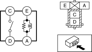
Type A
1. Remove the relay. (See RELAY LOCATION.)
2. Verify the continuity between relay terminals C and D.
If it can be verified, replace the relay. (See RELAY LOCATION.)
If it cannot be verified, go to the next step.
3. Verify the continuity between relay terminals E and A.
If it can be verified, go to the next step.
If it cannot be verified, replace the relay. (See RELAY LOCATION.)
4. Apply battery voltage to relay terminal E, and connect terminal A to ground.
5. Verify the continuity between relay terminals C and D.
If it cannot be verified, replace the relay. (See RELAY LOCATION.)
Type B
1. Remove the relay. (See RELAY LOCATION.)
2. Verify the continuity between relay terminals C and D.
If it can be verified, replace the relay. (See RELAY LOCATION.)
If it cannot be verified, go to the next step.
3. Verify the continuity between the relay terminals E and A.
If it can be verified, go to the next step.
If it cannot be verified, replace the relay. (See RELAY LOCATION.)
4. Verify the continuity between the relay terminals B and D.
If it can be verified, go to the next step.
If it cannot be verified, replace the relay. (See RELAY LOCATION.)
5. Apply battery voltage to relay terminal E, and connect terminal A to ground.
6. Verify the continuity between relay terminals C and D.
If it cannot be verified, replace the relay. (See RELAY LOCATION.)
Type C
1. Remove the relay. (See RELAY LOCATION.)
2. Verify the continuity between the relay terminals C and A.
If it can be verified, replace the relay. (See RELAY LOCATION.)
If it cannot be verified, go to the next step.
3. Verify the continuity between the relay terminals D and B.
If it can be verified, go to the next step.
If it cannot be verified, replace the relay. (See RELAY LOCATION.)
4. Apply battery voltage to relay terminal D, and connect terminal B to ground.
5. Verify the continuity between relay terminals C and A.< Previous Next >
If it cannot be verified, replace the relay. (See RELAY LOCATION.)


