DTC C101C:18 [EVP CONTROL UNIT]
| DTC |
C101C:18 |
Electric vacuum pump: drive current decrease |
| DETECTION CONDITION |
|
|
| FAIL-SAFE FUNCTION |
|
|
| POSSIBLE CAUSE |
|
|
| |
||
| Step |
Inspection |
Action |
|
| 1 |
RECORD SNAPSHOT DATA AND DIAGNOSTIC MONITORING TEST RESULTS TO UTILIZE WITH REPEATABILITY VERIFICATION NOTE:
|
— |
Go to the next step. |
| 2 |
VERIFY DTC REPEATABILITY NOTE:
|
Yes |
Go to Step 6. |
| No |
Go to the next step. |
||
| 3 |
DRIVE VEHICLE THEN VERIFY DTC REPEATABILITY BASED ON SERVICE QUESTIONING RESULTS AND SNAP SHOT DATA
|
Yes |
Go to Step 6. |
| No |
Go to the next step. |
||
| 4 |
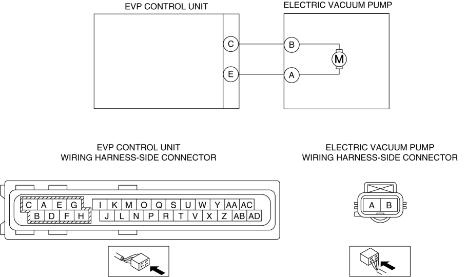
INSPECT ELECTRIC VACUUM PUMP CIRCUIT
|
Yes |
Go to the next step. |
| No |
Repair or replace the malfunctioning part, then go to Step 9. |
||
| 5 |
VERIFY DTC REPEATABILITY AND DETERMINE IF MALFUNCTION CAUSE IS EVP CONTROL UNIT
|
Yes |
Replace the EVP control unit, then go to Step 10. |
| No |
DTC troubleshooting completed. Explain to the customer that there are no malfunctions with the vehicle based on the contents of the servicing. |
||
| 6 |
INSPECT ELECTRIC VACUUM PUMP CONNECTOR CONDITION
|
Yes |
Go to the next step. |
| No |
Repair or replace the connector and/or terminals, then go to Step 9. |
||
| 7 |
INSPECT EVP CONTROL UNIT CONNECTOR CONDITION
|
Yes |
Go to the next step. |
| No |
Repair or replace the connector and/or terminals, then go to Step 9. |
||
| 8 |
INSPECT ELECTRIC VACUUM PUMP CIRCUIT FOR OPEN CIRCUIT
|
Yes |
Replace the electric vacuum pump, then go to the next step. |
| No |
Refer to the wiring diagram and verify whether or not there is a common connector in the followings:
Go to the next step. |
||
| 9 |
VERIFY DTC TROUBLESHOOTING COMPLETED
|
Yes |
Repeat the inspection from Step1. If the malfunction recurs, replace the EVP control unit, then go to the next step. |
| No |
Go to the next step. |
||
| 10 |
VERIFY NO DTC IS PRESENT
|
Yes |
Go to the applicable DTC inspection. (See DTC TABLE [EVP CONTROL UNIT].) |
| No |
DTC troubleshooting completed. |
||