ENGINE [SKYACTIV-G 2.0]
Special Features
For SKYACTIV-G 2.0, the following has been implemented to lower fuel consumption.
Sliding resistance*1 reduction
Rocker arm (with built-in needle roller bearing) adopted for cam-contact area
Reduced valve spring load
Narrowed down crankshaft journal
Optimized piston skirt shape
Lowered piston ring tension
Lowered drive belt tension
Suppressed chain tensioner load by stabilized timing chain behavior
Oil shower pipe adopted
Mechanical resistance loss reduction
Optimized oil passage
Optimized oil pump shape
Engine oil control adopted
Cooling loss reduction in early stage of combustion
Piston cavity adopted
Pumping loss*2 reduction
Variable valve timing mechanism adopted on both intake and exhaust sides for fine control of exhaust amount and internal EGR volume
Cooling efficiency improvement
Air seal cowl adopted
Optimized cooling fan shape
Optimized engine coolant passage
Optimized water pump impeller shape
Combustion efficiency improvement
Multiple hole-type fuel injectors adopted
High-pressure fuel pump adopted
The HLA has been adopted to achieve the maintenance-free valve clearance.
The 4-2-1 type exhaust pipes have been adopted for the exhaust manifold to achieve an engine with a high compression ratio.
L-jetronic*3 and D-jetronic*4 types have been adopted for the intake air amount measurement to achieve stable combustion free from abnormal combustion.
MAF sensor adopted
MAP sensor adopted
IAT sensor No.1 and No.2 adopted
To improve the fuel economy and emission performance, an electric variable valve timing control has been adopted for the intake side, and a hydraulic variable valve timing control for the exhaust side. The electric type is adopted for the intake side to achieve expanded valve overlap and delayed closing of the intake valve (enlarged intake valve opening angle).
Intake side: Electric variable valve timing control
Intake CMP sensor adopted
Electric variable valve timing motor/driver adopted
Electric variable valve timing relay adopted
Exhaust side: Hydraulic variable valve timing control
Exhaust CMP sensor adopted
Engine hydraulic pressure switching control has been adopted to reduce the oil pump operation load on the engine.
Engine oil solenoid valve adopted
To improve engine reliability, an ion sensor has been adopted which detects pre-ignition.
- *1
- Resistance (friction force) which occurs when objects slide. The larger the sliding resistance, the greater the energy loss.
- *2
- Energy loss due to resistance in each part during intake/exhaust process is called pumping loss.
- *3
- The intake air amount is directly detected by measuring the amount of intake air flow using the MAF sensor.
- *4
- The intake air amount is detected indirectly by measuring the intake manifold pressure (pressure between downstream of the throttle valve and intake manifold) using the MAP sensor.
Specification
| Item |
Specification |
||||
| MECHANICAL |
|||||
| Type |
Gasoline, 4???cycle |
||||
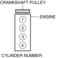
| Cylinder arrangement and number |
In-line, 4???cylinder |
||||
| Combustion chamber |
Pentroof |
||||
| Valve system |
DOHC, timing chain driven, 16 valves |
||||
| Displacement |
(ml ) |
1,997.6 {1,997.6} |
|||
| Bore × stroke |
(mm ) |
83.5 × 91.2 {3.29 × 3.59} |
|||
| Compression ratio |
13.0:1 |
||||
| Valve timing |
IN |
Open |
(°) |
BTDC 42???ATDC 32 |
|
| Close |
(°) |
ABDC 36???ABDC 110 |
|||
| EX |
Open |
(°) |
BBDC 56???BBDC 11 |
||
| Close |
(°) |
ATDC 5???ATDC 50 |
|||
| LUBRICATION SYSTEM |
|||||
| Type |
Force-fed type |
||||
| Oil pressure (reference value) [Coolant temperature: 80???90 °C {176???194 °F}] |
(kPa {kgf/cm2, psi} [rpm]) |
Lo: 110???175 {1.13???1.78, 16.0???25.3} [1,500] Hi: 300???430 {3.06???4.38, 43.6???62.3} [4,500] |
|||
| Oil pump |
Type |
Trochoid gear type |
|||
| Oil filter |
Type |
Full-flow |
|||
| Bypass pressure |
(kPa {kgf/cm2, psi}) |
78???118 {0.80???1.20, 12.0???17.1} |
|||
| Oil capacity (approx. quantity) |
Total (dry engine) |
(L {US qt, lmp qt}) |
5.0 {5.3, 4.4} |
||
| Oil replacement |
(L {US qt, lmp qt}) |
4.3 {4.5, 3.8} |
|||
| Oil and oil filter replacement |
(L {US qt, lmp qt}) |
4.1 {4.3, 3.6} |
|||
| COOLING SYSTEM |
|||||
| Type |
Water-cooled, Electromotive |
||||
| Coolant capacity (approx. quantity) |
(L {US qt, lmp qt}) |
AT: 5.9 {6.2, 5.2} MT: 6.0 {6.3, 5.3} |
|||
| Water pump |
Type |
Centrifugal, V-ribbed belt-driven |
|||
| Thermostat |
Type |
Wax type |
|||
| Opening temperature |
(°C {°F}) |
86.5???89.5 {188???193} |
|||
| Full-open temperature |
(°C {°F}) |
95 |
|||
| Full-open lift |
(mm ) |
8.5 {0.33} or more |
|||
| Radiator |
Type |
Corrugated fin type |
|||
| Cooling system cap |
Valve opening pressure |
(kPa {kgf/cm2, psi}) |
|
||
| Cooling fan type |
Type |
Electric type |
|||
| Number of blades |
9 |
||||
| Outer diameter |
(mm ) |
335 {13.2} |
|||
| Cooling fan motor output |
(W) |
AT: 160 MT: 120 |
|||
| FUEL SYSTEM |
|||||
| Fuel injector |
Type |
High resistance |
|||
| Fuel supply method |
Top-feed |
||||
| Drive types |
Electronic type |
||||
| Pressure regulator control pressure |
(kPa {kgf/cm2, psi}) |
Approx. 450 {4.59, 65.3} |
|||
| Fuel pump |
Type |
Electric type |
|||
| Fuel tank |
Capacity |
(L {US gal, lmp gal}) |
45.0 {11.9, 9.90} |
||
| EMISSION SYSTEM |
|||||
| Catalyst |
Type |
WU-TWC (monolith) TWC (monolith) |
|||
| EVAP control system |
Type |
Charcoal canister type |
|||
| PCV system |
Type |
Closed type |
|||
| CHARGING SYSTEM |
|||||
| Battery |
Voltage |
(V) |
12 |
||
| Type and capacity |
(A·h/20HR) |
46B24L (45) |
|||
| Generator |
Output |
(V-A) |
12-100 |
||
| IGNITION SYSTEM |
|||||
| Ignition system |
Type |
SEI |
|||
| Spark advance |
Electronic |
||||
| Firing order |
1???3???4???2 (all cylinders independent firing) |
||||
| Spark plug |
Type |
PE5R-18-110 PE5S-18-110 |
|||
| STARTING SYSTEM |
|||||
| Starter |
Type |
Coaxial reduction |
|||
| Output |
(kW) |
1.4 |
|||
| CONTROL SYSTEM |
|||||
| Neutral switch |
ON/OFF type switch |
||||
| CPP switch |
ON/OFF type switch |
||||
| MAF sensor |
Hot film |
||||
| IAT sensor No.1 |
Thermistor |
||||
| IAT sensor No.2 |
Thermistor |
||||
| MAP sensor |
Piezoresistance |
||||
| TP sensor |
Hall element |
||||
| APP sensor |
Electromagnetic induction action applied to non-contact type |
||||
| CKP sensor |
Magnetic resistance element |
||||
| Intake CMP sensor |
Magnetic resistance element |
||||
| Exhaust CMP sensor |
Magnetic resistance element |
||||
| ECT sensor |
Thermistor |
||||
| BARO sensor |
Piezoelectric element |
||||
| Fuel pressure sensor |
Strain gauge |
||||
| KS |
Piezoelectric element |
||||
| A/F sensor |
Zirconium element |
||||
| HO2S |
Zirconia element |
||||
| Oil pressure switch |
ON/OFF type switch |
||||
| Fuel tank pressure sensor |
Piezoelectric element |
||||
| Vacuum sensor 2 |
Piezoelectric element |
||||
| Ion sensor |
Ion detection circuit |
||||
Engine oil specification
| Item |
U.S.A., Canada and Puerto Rico |
Except U.S.A., Canada and Puerto Rico |
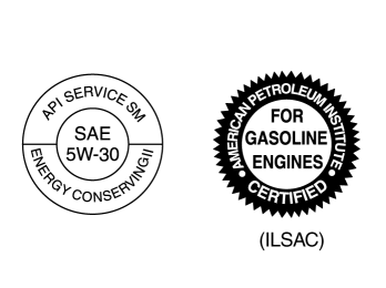
| Engine oil grade |
||
| API SM or ILSAC |
||
| Engine oil viscosity |
0W-20 |
5W-30 (If SAE 5W-30 engine oil is not available, use SAE 5W-20 engine oil.) |
| Fuel |
Octane Rating* (Anti-knock index) |
| Regular unleaded fuel |
91 [(R+M)/2 method] or above (96 RON or above) |
- *
- U.S. federal law requires that octane ratings be posted on gasoline station pumps.


