TCM
Purpose/Function
The TCM detects the vehicle conditions and performs calculations and processing based on input information from each type of sensor and switch.
Outputs control signals to each solenoid valve so that each type of control is optimally implemented according to the vehicle conditions.
Function Table
| Control item |
Main control content |
|||
| Shift point control |
Automatic shift control (D position) |
Driving mode |
Normal mode |
|
| SPORT mode (with drive selection switch) |
|
|||
| Active Adaptive Shift (AAS) mode |
|
|||
| Direct mode control (D range) |
|
|||
| Manual shift control (M position) |
|
|||
| Neutral control |
|
|||
| Reverse control |
|
|||
| Shift pressure control |
Line pressure control |
|
||
| Learning control |
|
|||
| Torque converter clutch (TCC) control, slip control |
|
|||
| Engine-transmission integration control |
|
|||
| On-board diagnostic system |
|
|||
Construction
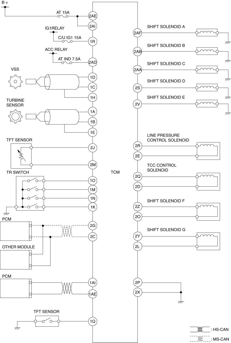
System wiring diagram
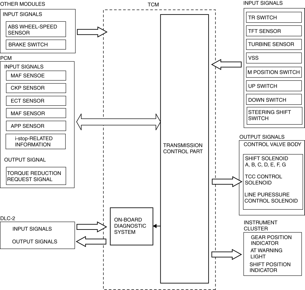
Block diagram
Operation
Input/Output signal and related controls
| Component |
Control |
|||||||||||
| Automatic shift control (D position) |
Direct mode control (D range) |
Manual shift control (M position) |
Neutral control |
Reverse control |
Line pressure control |
Learning control |
Torque converter clutch (TCC) control, slip control |
Engine-transmission integration control |
On-board diagnostic system |
|||
| Input |
VSS |
X |
X |
X |
X |
X |
X |
|
X |
|
X |
|
| Turbine sensor |
X |
|
X |
X |
X |
X |
X |
X |
X |
X |
||
| TR switch |
X |
X |
X |
X |
X |
|
|
|
|
|
||
| TFT sensor |
X |
|
X |
|
X |
|
X |
|
|
|||
| CAN |
M range switch |
|
|
X |
|
X |
|
|
|
|
||
| Up switch |
|
|
X |
|
X |
|
|
|
|
|||
| Down switch |
|
|
X |
|
X |
|
|
|
|
|||
| Steering shift switch |
|
X |
X |
|
X |
|
|
|
|
|||
| Brake switch |
|
|
|
|
|
|
X |
|
|
|||
| Throttle opening signal (APP sensor) |
X |
X |
X |
X |
|
X |
|
|
X |
X |
||
| Engine speed signal (Eccentric shaft position sensor) |
|
X |
|
|
X |
X |
X |
X |
X |
|||
| Engine torque signal (MAF sensor) |
|
|
|
|
X |
X |
|
X |
X |
|||
| Engine coolant temperature signal (ECT sensor) |
X |
|
|
|
|
|
X |
|
X |
|||
| Drive selection signal |
X |
|
|
|
|
|
|
|
|
|||
| Wheel speed signal (wheel speed sensor) |
X |
X |
|
X |
|
|
|
|
|
|
||
| Output |
ON/OFF type |
Shift solenoid A |
X |
X |
X |
|
X |
|
|
X |
||
| Shift solenoid B |
X |
X |
X |
X |
|
X |
|
|
X |
|||
| Shift solenoid C |
X |
X |
X |
X |
|
X |
|
|
X |
|||
| Shift solenoid D |
X |
X |
X |
|
X |
|
|
X |
||||
| Shift solenoid E |
X |
X |
X |
X |
X |
|
X |
|
|
X |
||
| Linear type |
Line pressure control solenoid |
X |
X |
X |
X |
X |
|
|
X |
|||
| TCC control solenoid |
|
|
|
|
|
X |
|
X |
||||
| Shift solenoid F |
X |
X |
X |
X |
X |
X |
|
|
X |
|||
| Shift solenoid G |
X |
X |
X |
X |
X |
X |
|
|
X |
|||
| CAN |
AT warning light |
X |
|
X |
|
|
|
|
X |
|||
| Torque reduction request signal |
|
|
|
|
|
|
X |
|
||||
| Speedometer signal |
|
|
|
|
|
|
|
|
||||
| Electric AT oil pump driver |
|
|
|
|
|
|
|
|
||||

