AUDIO AMPLIFIER [WITH CENTER DISPLAY]
Purpose, Function
The audio signal (analog voltage waveform) output from the unit equipped on the vehicle is converted into a digital pulse. The converted digital pulse signal is amplified, converted to an analog signal again, and sent to the speakers.
Construction
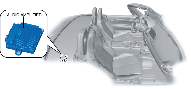
The audio amplifier is located in the side shelf (RH).
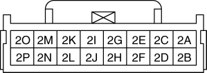
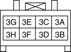
Terminal Layout and Signal
| Terminal |
Signal |
|
| 1A |
— |
|
| 1B |
— |
|
| 1C |
— |
|
| 1D |
— |
|
| 1E |
Front speaker input LH (-) |
|
| 1F |
Front speaker input LH (+) |
|
| 1G |
Front speaker input RH (-) |
|
| 1H |
Front speaker input RH (+) |
|
| 1I |
Rear speaker input LH (-) |
|
| 1J |
Rear speaker input LH (+) |
|
| 1K |
Rear speaker input RH (-) |
|
| 1L |
Rear speaker input RH (+) |
|
| 1M |
— |
|
| 1N |
— |
|
| 1O |
— |
|
| 1P |
— |
|
| 2A |
— |
|
| 2B |
— |
|
| 2C |
Passenger-side headrest speaker output RH (+) |
|
| 2D |
Audio amplifier control |
|
| 2E |
Passenger-side headrest speaker output RH (-) |
|
| 2F |
Top lock switch input |
|
| 2G |
Passenger-side headrest speaker output LH (+) |
|
| 2H |
Pulse width modulation (PWM) control |
|
| 2I |
Passenger-side headrest speaker output LH (-) |
|
| 2J |
— |
|
| 2K |
Driver-side headrest speaker output RH (-) |
|
| 2L |
HS-CAN_H |
|
| 2M |
Driver-side headrest speaker output RH (+) |
|
| 2N |
HS-CAN_L |
|
| 2O |
Driver-side headrest speaker output LH (+) |
|
| 2P |
Driver-side headrest speaker output LH (-) |
|
| 3A |
B+ |
|
| 3B |
Ground |
|
| 3C |
Tweeter output RH (+) |
|
| 3D |
Tweeter output RH (-) |
|
| 3E |
Woofer output (+) |
|
| 3F |
Woofer output (-) |
|
| 3G |
Tweeter output LH (+) |
|
| 3H |
Tweeter output LH (-) |
|
Operation
The audio amplifier amplifies the audio signal sent (1) from the tuner and amp unit (TAU) and sends (2) it to the speakers.
The speakers produce (3) audio based on the audio signal sent from the TAU.
Fail-safe
< Previous Next >
Not applicable


