DSC HU/CM INSPECTION
1. Disconnect the DSC HU/CM connector. (See DSC HU/CM REMOVAL/INSTALLATION.)
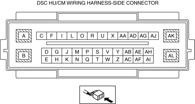
2. Measure the voltage or continuity of the DSC HU/CM wiring harness-side connctor using a tester.
Terminal Voltage Table (Reference)
| Terminal |
Connected to |
Measured item |
Test condition or measured terminal |
Specification (Reference) |
Inspection item |
| A |
Battery |
Voltage |
Under any condition |
B+ |
|
| B |
Battery |
Voltage |
Under any condition |
B+ |
|
| C |
CAN related module |
Because this terminal is for communication, determination using terminal voltage inspection is not possible. Perform the inspection using the DTC inspection. |
|||
| D |
CAN related module |
Because this terminal is for communication, determination using terminal voltage inspection is not possible. Perform the inspection using the DTC inspection. |
|||
| E |
— |
— |
— |
— |
— |
| F |
— |
— |
— |
— |
— |
| G |
— |
— |
— |
— |
— |
| H |
— |
— |
— |
— |
— |
| I |
IG1 relay |
Voltage |
Ignition off |
1.0 V or less |
|
| Ignition ON (engine off) |
B+ |
||||
| J |
RF ABS wheel-speed sensor |
Continuity |
DSC HU/CM terminal J—RF ABS wheel-speed sensor terminal B |
Continuity detected |
|
| K |
RF ABS wheel-speed sensor |
Continuity |
DSC HU/CM terminal K—RF ABS wheel-speed sensor terminal A |
Continuity detected |
|
| L |
RR ABS wheel-speed sensor |
Continuity |
DSC HU/CM terminal L—RR ABS wheel-speed sensor terminal B |
Continuity detected |
|
| M |
RR ABS wheel-speed sensor |
Continuity |
DSC HU/CM terminal M—RR ABS wheel-speed sensor terminal A |
Continuity detected |
|
| N |
— |
— |
— |
— |
— |
| O |
— |
— |
— |
— |
— |
| P |
LR ABS wheel-speed sensor |
Continuity |
DSC HU/CM terminal P—LR ABS wheel-speed sensor terminal B |
Continuity detected |
|
| Q |
— |
— |
— |
— |
— |
| R |
LR ABS wheel-speed sensor |
Continuity |
DSC HU/CM terminal R—LR ABS wheel-speed sensor terminal A |
Continuity detected |
|
| S |
LF ABS wheel-speed sensor |
Continuity |
DSC HU/CM terminal S—LF ABS wheel-speed sensor terminal B |
Continuity detected |
|
| T |
— |
— |
— |
— |
— |
| U |
— |
— |
— |
— |
— |
| V |
— |
— |
— |
— |
— |
| W |
LF ABS wheel-speed sensor |
Continuity |
DSC HU/CM terminal W—LF ABS wheel-speed sensor terminal A |
Continuity detected |
|
| X |
— |
— |
— |
— |
— |
| Y |
— |
— |
— |
— |
— |
| Z |
— |
— |
— |
— |
— |
| AA |
— |
— |
— |
— |
— |
| AB |
— |
— |
— |
— |
— |
| AC |
— |
— |
— |
— |
— |
| AD |
— |
— |
— |
— |
— |
| AE |
— |
— |
— |
— |
— |
| AF |
— |
— |
— |
— |
— |
| AG |
— |
— |
— |
— |
— |
| AH |
— |
— |
— |
— |
— |
| AI |
— |
— |
— |
— |
— |
| AJ |
— |
— |
— |
— |
— |
| AK |
Ground point |
Continuity |
DSC HU/CM terminal AK—ground point |
Continuity detected |
|
| AL |
Ground point |
Continuity |
DSC HU/CM terminal AL—ground point |
Continuity detected |
|