MX5 mk4 Manual
Home bodyshop manual wiring diagram workshop manual service highlights transmission overhaul

Knowledge Base

Free to use workshop manual for your 2015+ Mk4 'ND' Mazda MX-5
Home


< Previous   Next >

TCM INSPECTION [SJ6A-EL]

NOTE:

  • The TCM terminal voltage can vary with conditions when measuring and changes due to age deterioration on the vehicle, causing false diagnosis. Therefore a comprehensive inspection of the input and output systems, and the TCM is necessary to determine where the malfunction occurs.

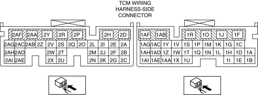
1. Measure the terminal voltage of the TCM using a tester.

Terminal Voltage Table (Reference)

Terminal

Connected to

Test Condition

Specification

Inspection item(s)

1A

Turbine sensor

  • Inspect using the wave profile.

    (See Inspection Using An Oscilloscope (Reference).)

  • Inspect the turbine sensor

    (See TURBINE SENSOR INSPECTION [SJ6A-EL])

  • Inspect the related wiring harness

1B

Turbine sensor

Ignition switch ON

Approx. 2.5 V

  • Inspect the turbine sensor

    (See TURBINE SENSOR INSPECTION [SJ6A-EL])

  • Inspect the related wiring harness

1C

VSS

Ignition switch ON

Approx. 2.5 V

  • Inspect the VSS

    (See VEHICLE SPEED SENSOR (VSS) INSPECTION [SJ6A-EL])

  • Inspect the related wiring harness

1D

VSS

  • Inspect using the wave profile.

    (See Inspection Using An Oscilloscope (Reference).)

  • Inspect the VSS

    (See VEHICLE SPEED SENSOR (VSS) INSPECTION [SJ6A-EL])

  • Inspect the related wiring harness

1E

Sensor shield

Under any condition

Below 1.0 V

  • Inspect the related wiring harness

1F

???

???

???

???

1G

???

???

???

???

1H

Sensor shield

Under any condition

Below 1.0 V

  • Inspect the related wiring harness

1I

???

???

???

???

1J

???

???

???

???

1K

TR switch

P position

B+

  • Inspect the TR switch

    (See TRANSMISSION RANGE (TR) SWITCH INSPECTION [SJ6A-EL])

  • Inspect the related wiring harness

R position

B+

N position

B+

D position

Below 1.0 V

M position

Below 1.0 V

1L

???

???

???

???

1M

TR switch

P position

B+

  • Inspect the TR switch

    (See TRANSMISSION RANGE (TR) SWITCH INSPECTION [SJ6A-EL])

  • Inspect the related wiring harness

R position

Below 1.0 V

N position

B+

D position

B+

M position

B+

1N

TR switch

P position

B+

  • Inspect the TR switch

    (See TRANSMISSION RANGE (TR) SWITCH INSPECTION [SJ6A-EL])

  • Inspect the related wiring harness

R position

B+

N position

Below 1.0 V

D position

B+

M position

B+

1O

TR switch

P position

Below 1.0 V

  • Inspect the TR switch

    (See TRANSMISSION RANGE (TR) SWITCH INSPECTION [SJ6A-EL])

  • Inspect the related wiring harness

R position

B+

N position

B+

D position

B+

M position

B+

1P

???

???

???

???

1Q

TFT check connector

Under any condition

B+

  • Inspect the related wiring harness

1R

IG1 relay

Ignition switch OFF

Below 1.0 V

  • Inspect the IG1 relay

    (See RELAY INSPECTION)

  • Inspect the related wiring harness

Ignition switch ON

B+

1S

???

???

???

???

1T

???

???

???

???

1U

???

???

???

???

1V

???

???

???

???

1W

???

???

???

???

1X

???

???

???

???

1Y

???

???

???

???

1Z

???

???

???

???

1AA

???

???

???

???

1AB

???

???

???

???

1AC

???

???

???

???

1AD

???

???

???

???

1AE

CAN related module

Because this terminal is for communication, determination using terminal voltage inspection is not possible. Perform the inspection using the DTC inspection.

1AF

???

???

???

???

1AG

???

???

???

???

1AH

???

???

???

???

1AI

CAN related module

Because this terminal is for communication, determination using terminal voltage inspection is not possible. Perform the inspection using the DTC inspection.

2A

???

???

???

???

2B

???

???

???

???

2C

CAN related module

Because this terminal is for communication, determination using terminal voltage inspection is not possible. Perform the inspection using the DTC inspection.

2D

TCC control solenoid

  • Inspect using the wave profile.

    (See Inspection Using An Oscilloscope (Reference).)

  • Inspect the TCC control solenoid

    (See SOLENOID VALVE INSPECTION [SJ6A-EL])

  • Inspect the related wiring harness

2E

Line pressure control solenoid

Idle and selector lever is at P position or N position

Below 1.0 V

  • Inspect the line pressure control solenoid

    (See SOLENOID VALVE INSPECTION [SJ6A-EL])

  • Inspect the related wiring harness

2F

???

???

???

???

2G

CAN related module

Because this terminal is for communication, determination using terminal voltage inspection is not possible. Perform the inspection using the DTC inspection.

2H

???

???

???

???

2I

???

???

???

???

2J

TFT sensor

ATF temperature 20°C {68°F}

Approx. 3.0 V

  • Inspect the TFT sensor

    (See TRANSMISSION FLUID TEMPERATURE (TFT) SENSOR INSPECTION [SJ6A-EL])

  • Inspect the related wiring harness

ATF temperature 40°C {104°F}

Approx. 2.1 V

ATF temperature 60°C {140°F}

Approx. 1.4 V

2K

???

???

???

???

2L

Shift solenoid G

  • Inspect using the wave profile.

    (See Inspection Using An Oscilloscope (Reference).)

  • Inspect the shift solenoid G

    (See SOLENOID VALVE INSPECTION [SJ6A-EL])

  • Inspect the related wiring harness

2M

TFT sensor

Under any condition

Below 1.0 V

  • Inspect the TFT sensor

    (See TRANSMISSION FLUID TEMPERATURE (TFT) SENSOR INSPECTION [SJ6A-EL])

  • Inspect the related wiring harness

2N

???

???

???

???

2O

Shift solenoid F

  • Inspect using the wave profile.

    (See Inspection Using An Oscilloscope (Reference).)

  • Inspect the shift solenoid F

    (See SOLENOID VALVE INSPECTION [SJ6A-EL])

  • Inspect the related wiring harness

2P

GND

Under any condition

Below 1.0 V

  • Inspect the related wiring harness

2Q

TCC control solenoid

  • Inspect using the wave profile.

    (See Inspection Using An Oscilloscope (Reference).)

  • Inspect the TCC control solenoid

    (See SOLENOID VALVE INSPECTION [SJ6A-EL])

  • Inspect the related wiring harness

2R

Line pressure control solenoid

  • Inspect using the wave profile.

    (See Inspection Using An Oscilloscope (Reference).)

  • Inspect the line pressure control solenoid

    (See SOLENOID VALVE INSPECTION [SJ6A-EL])

  • Inspect the related wiring harness

2S

Shift solenoid D

1GR

Below 1.0 V

  • Inspect the shift solenoid D

    (See SOLENOID VALVE INSPECTION [SJ6A-EL])

  • Inspect the related wiring harness

2GR

Below 1.0 V

3GR

Below 1.0 V

4GR

Below 1.0 V

5GR

B+

6GR

B+

2T

???

???

???

???

2U

???

???

???

???

2V

Shift solenoid E

1GR

B+

  • Inspect the shift solenoid E

    (See SOLENOID VALVE INSPECTION [SJ6A-EL])

  • Inspect the related wiring harness

2GR

B+

3GR

B+

4GR

B+

5GR

Below 1.0 V

6GR

Below 1.0 V

2W

???

???

???

???

2X

GND

Under any condition

Below 1.0 V

  • Inspect the related wiring harness

2Y

Shift solenoid G

  • Inspect using the wave profile.

    (See Inspection Using An Oscilloscope (Reference).)

  • Inspect the shift solenoid G

    (See SOLENOID VALVE INSPECTION [SJ6A-EL])

  • Inspect the related wiring harness

2Z

Shift solenoid F

  • Inspect using the wave profile.

    (See Inspection Using An Oscilloscope (Reference).)

  • Inspect the shift solenoid F

    (See SOLENOID VALVE INSPECTION [SJ6A-EL])

  • Inspect the related wiring harness

2AA

Shift solenoid C

1GR

B+

  • Inspect the shift solenoid C

    (See SOLENOID VALVE INSPECTION [SJ6A-EL])

  • Inspect the related wiring harness

2GR

B+

3GR

B+

4GR

Below 1.0 V

5GR

Below 1.0 V

6GR

Below 1.0 V

2AB

Shift solenoid B

1GR

B+

  • Inspect the shift solenoid B

    (See SOLENOID VALVE INSPECTION [SJ6A-EL])

  • Inspect the related wiring harness

2GR

B+

3GR

Below 1.0 V

4GR

Below 1.0 V

5GR

Below 1.0 V

6GR

B+

2AC

???

???

???

???

2AD

ACC relay

Ignition switch OFF

Below 1.0 V

  • Inspect the ACC relay

    (See RELAY INSPECTION)

  • Inspect the related wiring harness

Ignition switch ACC

B+

2AE

Battery

Under any condition

B+

  • Inspect the Battery

    (See BATTERY INSPECTION)

  • Inspect the related wiring harness

2AF

Shift solenoid A

1GR

Below 1.0 V

  • Inspect the shift solenoid A

    (See SOLENOID VALVE INSPECTION [SJ6A-EL])

  • Inspect the related wiring harness

2GR

B+

3GR

B+

4GR

B+

5GR

B+

6GR

B+

2AG

???

???

???

???

2AH

???

???

???

???

2AI

Battery

Under any condition

B+

  • Inspect the Battery

    (See BATTERY INSPECTION)

  • Inspect the related wiring harness

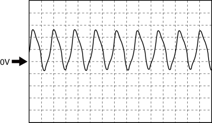
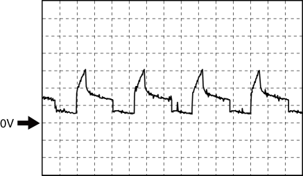
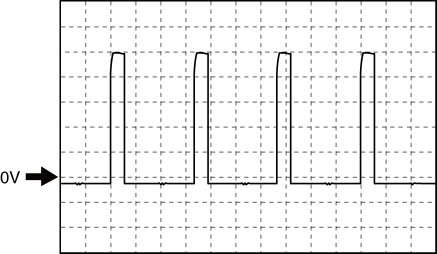
Inspection Using An Oscilloscope (Reference)

Turbine sensor (+)
  • TCM terminal: 1A

  • Oscilloscope setting: 2 V/DIV (Y) 2 ms/DIV (X)

  • Measuring condition: Vehicle speed at 30 km/h {19 mph} (D position 1GR)

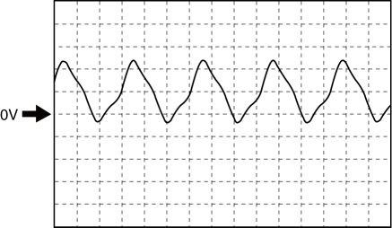
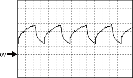
Vehicle speed (+)
  • TCM terminal: 1D

  • Oscilloscope setting: 2.5 V/DIV (Y) 1 ms/DIV (X)

  • Measuring condition: Vehicle speed at 30 km/h {19 mph} (D position 1GR)

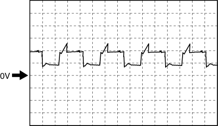
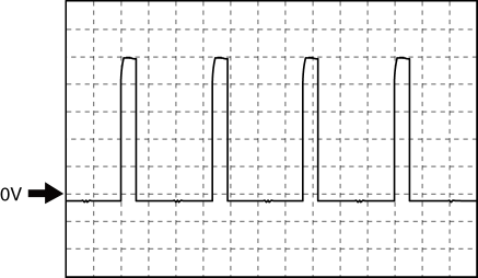
TCC control solenoid control (-)
  • TCM terminal: 2D

  • Oscilloscope setting: 50 mV/DIV (Y) 1 ms/DIV (X)

  • Measuring condition: P, N position, Idle

Shift solenoid G control (-)
  • TCM terminal: 2L

  • Oscilloscope setting: 50 mV/DIV (Y) 1ms/DIV (X)

  • Measuring condition: M position 1GR

Shift solenoid F control (-)
  • TCM terminal: 2O

  • Oscilloscope setting: 100 mV/DIV (Y) 1 ms/DIV (X)

  • Measuring condition: M position 5GR

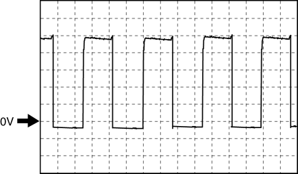
TCC control solenoid control (+)
  • TCM terminal: 2Q

  • Oscilloscope setting: 2.5 V/DIV (Y) 1 ms/DIV (X)

  • Measuring condition: P, N position, Idle

Line pressure control solenoid control (+)
  • TCM terminal: 2R

  • Oscilloscope setting: 2.5 V/DIV (Y) 1 ms/DIV (X)

  • Measuring condition: P, N position, Idle

Shift solenoid G control (+)
  • TCM terminal: 2Y

  • Oscilloscope setting: 2.5 V/DIV (Y) 1 ms/DIV (X)

  • Measuring condition: M position 1GR

Shift solenoid F control (+)
  • TCM terminal: 2Z

  • Oscilloscope setting: 2.5 V/DIV (Y) 1 ms/DIV (X)

  • Measuring condition: M position 5GR

< Previous   Next >
 

Free to use workshop manual for your 2015+ Mk4 'ND' Mazda MX-5

COPYRIGHT NOTICE:
This fan site is not affiliated with Mazda, and is intended for personal, or commercial use only. The content of our web pages is for general information purposes only and is presented “as is”. We give no assurance or warranty regarding the accuracy of the contents. Readers should do their due diligence and seek the advice of an appropriately certified automotive technician before attempting any steps on this site. Original content provided by Mazda North America. The content of the manual is copyright under DMCA to: full.metal.resistor@gmail.com
LIMITATION OF LIABILITY:
We accept no responsibility for errors, inaccuracies, or omissions found on these pages. Additionally, we hereby exclude liability for any demands, claims, damages or losses of any kind with regard to any content or information provided on our web-site, including but not limited to incidental or consequential damages, direct or indirect loss, compensatory damages, loss of profits, or otherwise. By using this manual you assume full liablity for any procedures carried out on your vehicle, and are responsible for the vehicle remaining road legal and safe.
Site design © MX5 Docs 2019
Privacy policy
Cookies
X
We use cookies to improve your experience on
our site. By using our site you consent to cookies.
Learn more
I Agree