DTC: 16:Er11, 16:Er12, 26:Er81 [AUDIO UNIT]
| Description |
|
| Detection condition |
|
| Fail-safe |
|
| Possible cause |
|
| |
|
CAUTION:
Diagnostic Procedure
When disconnecting the connector, verify that there is no looseness, damage, deformation, corrosion, or poor connection of the connector terminals.
| Step |
Inspection |
Action |
|
| 1 |
INSPECT FOR POWER SUPPLY-RELATED MALFUNCTION
|
Yes |
NOTE:
Repair the malfunctioning location according to the applicable DTC troubleshooting. |
| No |
Go to the next step. |
||
| 2 |
INSPECT CAN_H SIDE CIRCUIT OF LOCAL MS-CAN FOR SHORT TO POWER SUPPLY
|
Yes |
A short to power supply in CAN_H side of LOCAL MS-CAN has occurred.
|
| No |
Go to the next step. |
||
| 3 |
INSPECT CAN_L SIDE CIRCUIT OF LOCAL MS-CAN FOR SHORT TO GROUND
|
Yes |
A short to ground in CAN_L side of LOCAL MS-CAN has occurred.
|
| No |
Go to the next step. |
||
| 4 |
INSPECT BETWEEN LOCAL MS-CAN_L AND LOCAL MS-CAN_H SIDE CIRCUITS FOR SHORT BETWEEN CIRCUITS
|
Yes |
Go to Step 9. (LOCAL MS-CAN is normal) |
| No |
|
||
| 5 |
INSPECT RELATED WIRING HARNESS (SHORT TO POWER SUPPLY)
|
Yes |
Go to Step 9. |
| No |
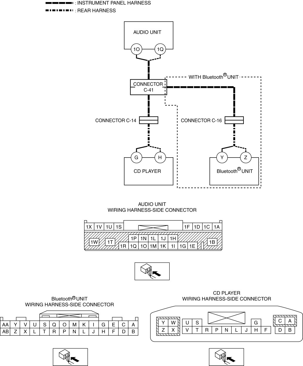
Refer to the wiring diagram and verify whether or not there is a common connector between the following terminals:
Go to Step 11. |
||
| 6 |
INSPECT RELATED WIRING HARNESS (SHORT TO GROUND)
|
Yes |
Refer to the wiring diagram and verify whether or not there is a common connector between the following terminals:
Go to Step 11. |
| No |
Go to Step 9. |
||
| 7 |
INSPECT RELATED WIRING HARNESS (LINE-TO-LINE SHORT CIRCUIT)
|
Yes |
Refer to the wiring diagram and verify whether or not there is a common connector between the following terminals:
Go to Step 11. |
| No |
Go to Step 9. |
||
| 8 |
INSPECT RELATED WIRING HARNESS (OPEN CIRCUIT)
|
Yes |
Refer to the wiring diagram and verify whether or not there is a common connector between the following terminals:
Go to Step 11. |
| No |
Go to Step 9. |
||
| 9 |
VERIFY IF MALFUNCTIONING LOCATION IS CD PLAYER DEPENDING ON REPEATABILITY
|
Yes |
Replace the CD player, then go to the next step. |
| No |
Go to Step 12. |
||
| 10 |
VERIFY IF MALFUNCTIONING LOCATION IS Bluetooth® UNIT DEPENDING ON REPEATABILITY NOTE:
|
Yes |
Replace the Bluetooth® unit, then go to the next step. |
| No |
Go to Step 12. |
||
| 11 |
VERIFY THAT REPAIRS HAVE BEEN COMPLETED
|
Yes |
Repeat the inspection from Step 1.
Go to the next step. |
| No |
Go to the next step. |
||
| 12 |
VERIFY IF OTHER DTCs DISPLAYED
|
Yes |
Repair or replace the malfunctioning part according to the applicable DTC troubleshooting. (See DTC TABLE [AUDIO UNIT].) |
| No |
DTC troubleshooting completed. |
||