MX5 mk4 Manual
Home bodyshop manual wiring diagram workshop manual service highlights transmission overhaul

Knowledge Base

Free to use workshop manual for your 2015+ Mk4 'ND' Mazda MX-5
Home


< Previous   Next >

DTC C101A:00 [EVP CONTROL UNIT]

DTC

C101A:00

Vacuum sensor 1/ Vacuum sensor 2 correlation problem

DETECTION CONDITION

  • Vacuum sensor 1 and 2 values are compared and the difference is 5 kPa {38 mmHg, 2 inHg} or more for a continuous 1 s.

FAIL-SAFE FUNCTION

  • Refer to “Fail-safe function table”. (See DTC TABLE [EVP CONTROL UNIT].)

POSSIBLE CAUSE

  • Malfunctions (open circuit, short circuit, connection malfunction) in the following wiring harnesses and connectors

    • Vacuum sensor 1 terminal A—EVP control unit terminal AA

    • Vacuum sensor 1 terminal C—EVP control unit terminal AC

    • Vacuum sensor 1 terminal B—EVP control unit terminal Y

    • Vacuum sensor 2 terminal A—PCM terminal 2BG

    • Vacuum sensor 2 terminal C—PCM terminal 2Q

    • Vacuum sensor 2 terminal B—PCM terminal 2AH

  • Vacuum sensor 1 malfunction

  • Vacuum sensor 2 malfunction

  • EVP control unit malfunction

Diagnostic Procedure

Step

Inspection

Action

1

RECORD SNAPSHOT DATA AND DIAGNOSTIC MONITORING TEST RESULTS TO UTILIZE WITH REPEATABILITY VERIFICATION

NOTE:

  • Recording can be facilitated using the screen capture function of the PC.

  • Record the snapshot data and DIAGNOSTIC MONITORING TEST RESULTS (fuel system related) on the repair order.

—

Go to the next step.

2

VERIFY IF DIAGNOSTIC RESULT IS AFFECTED BY OTHER RELATED DTCs OCCURRING
  • Using the M-MDS, perform the EVP control unit and PCM DTC inspection.I

    (See DTC TABLE [PCM (SKYACTIV-G 2.0)].)

    (See DTC INSPECTION [EVP CONTROL UNIT].)

  • Are following DTCs detected?

    • EVP control unit:
    • C101B:16

    • C101B:17

      PCM:
    • P0555:00

Yes

Go to the applicable DTC inspection.

(See DTC C101B:16/C101B:17 [EVP CONTROL UNIT].)

(See DTC P0555:00 [PCM (SKYACTIV-G 2.0)].)

No

Go to the next step.

3

DETERMINE WHETHER MALFUNCTION IS PAST OR PRESENT
  • Switch the ignition ON (engine off).

  • Access the VS1 and VS2 PIDs using the M-MDS.

  • Start the engine.

  • Compare the values of PIDs VS1 and VS2.

  • Is the difference between PIDs VS1 and VS2 5 kPa {38 mmHg, 2 inHg} or more?

Yes

Go to Step 8.

No

Go to the next step.

4

VERIFY DTC REPEATABILITY
  • Switch the ignition ON (engine off).

  • Access the VS1 and VS2 PIDs using the M-MDS.

  • Access the simulation item VPS_FBK using the M-MDS.

  • Verify PID VS1 and VS2 when operating simulation item VPS_FBK.

  • Do the values in PIDs VS1 and VS2 change when the wiring harnesses for vacuum sensor 1 and 2 are shaken?

Yes

    If PID VS1 value changes:
  • Go to Step 8.

    If PID VS2 value changes:
  • Go to Step 10.

No

Go to the next step.

5

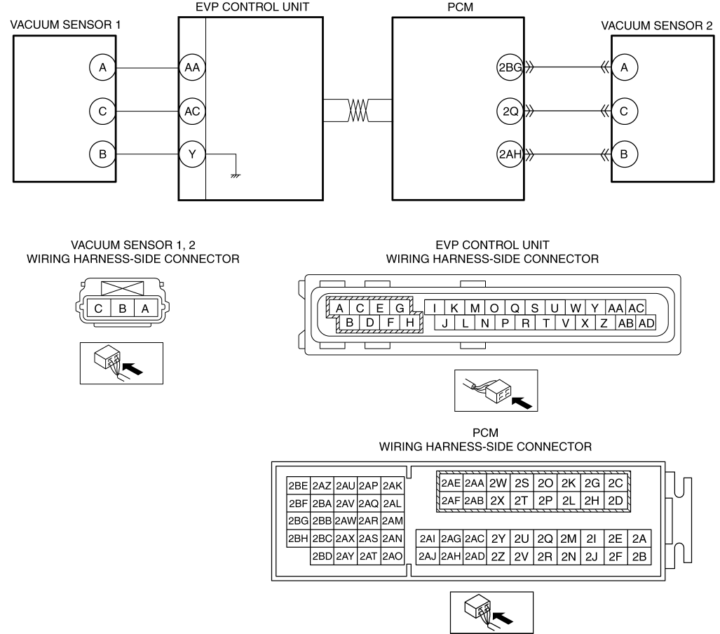
INSPECT VACUUM SENSOR 1 AND VACUUM SENSOR 2 CIRCUITS
  • Switch the ignition OFF.

  • Inspect the wiring harness between the following terminals for an open circuit, short circuit or connector connection malfunction.

    • Vacuum sensor 1 terminal A (wiring harness-side)—EVP control unit terminal AA (wiring harness-side)

    • Vacuum sensor 1 terminal C (wiring harness-side)—EVP control unit terminal AC (wiring harness-side)

    • Vacuum sensor 1 terminal B (wiring harness-side)—EVP control unit terminal Y (wiring harness-side)

    • Vacuum sensor 2 terminal A (wiring harness-side)—PCM terminal 2BG (wiring harness-side)

    • Vacuum sensor 2 terminal C (wiring harness-side)—PCM terminal 2Q (wiring harness-side)

    • Vacuum sensor 2 terminal B (wiring harness-side)—PCM terminal 2AH (wiring harness-side)

  • Are connectors and harnesses normal?

Yes

Go to the next step.

No

Repair or replace the malfunctioning part, then go to Step12.

6

DRIVE VEHICLE THEN VERIFY DTC REPEATABILITY BASED ON SERVICE QUESTIONING RESULTS AND SNAP SHOT DATA
  • Switch the ignition ON (engine off).

  • Access the VS1 and VS2 PIDs using the M-MDS.

  • Compare the service questions content and snap shot data driving conditions when the vehicle is driven with the values of PID VS1 and VS2.

  • Is the difference between PIDs VS1 and VS2 5 kPa {38 mmHg, 2 inHg} or more?

Yes

Go to Step 8.

No

Go to the next step.

7

DRIVE VEHICLE THEN VERIFY DTC REPEATABILITY BASED ON SERVICE QUESTIONING RESULTS AND SNAP SHOT DATA
  • Using the M-MDS, clear the DTC from the EVP control unit.

    (See CLEARING DTC [EVP CONTROL UNIT].)

  • Drive the vehicle based on the service questions content and snap shot data driving conditions again.

  • Using the M-MDS, perform the EVP control unit DTC inspection.

    (See DTC INSPECTION [EVP CONTROL UNIT].)

  • Is the same DTC present?

Yes

Replace the EVP control unit, then go to Step 13.

(See EVP CONTROL UNIT REMOVAL/INSTALLATION.)

No

DTC troubleshooting completed.

Explain to the customer that there are no malfunctions with the vehicle based on the contents of the servicing.

8

INSPECT VACUUM SENSOR 1 CIRCUIT
  • Switch the ignition OFF.

  • Inspect the wiring harness between the following terminals for an open circuit, short circuit or connector connection malfunction.

    • Vacuum sensor 1 terminal A (wiring harness-side)—EVP control unit terminal AA (wiring harness-side)

    • Vacuum sensor 1 terminal C (wiring harness-side)—EVP control unit terminal AC (wiring harness-side)

    • Vacuum sensor 1 terminal B (wiring harness-side)—EVP control unit terminal Y (wiring harness-side)

  • Are inspection results normal?

Yes

Go to the next step.

No

Repair or replace the malfunctioning part, then go to Step 12.

9

INSPECT VACUUM SENSOR 1
  • Inspect the vacuum sensor 1.

    (See VACUUM SENSOR 1 INSPECTION.)

  • Is the vacuum sensor 1 normal?

Yes

Go to the next step.

No

Replace the power brake unit, then go to Step 12.

(See POWER BRAKE UNIT REMOVAL/INSTALLATION.)

10

INSPECT VACUUM SENSOR 2 CIRCUIT
  • Switch the ignition OFF.

  • Inspect the wiring harness between the following terminals for an open circuit, short circuit or connector connection malfunction.

    • Vacuum sensor 2 terminal A (wiring harness-side)—PCM terminal 2BG (wiring harness-side)

    • Vacuum sensor 2 terminal C (wiring harness-side)—PCM terminal 2Q (wiring harness-side)

    • Vacuum sensor 2 terminal B (wiring harness-side)—PCM terminal 2AH (wiring harness-side)

  • Are inspection results normal?

Yes

Go to the next step.

No

Repair or replace the malfunctioning part, then go to Step 12.

11

INSPECT VACUUM SENSOR 2
  • Inspect the vacuum sensor 2.

    (See VACUUM SENSOR 2 INSPECTION [SKYACTIV-G 2.0].)

  • Is the vacuum sensor 2 normal?

Yes

Go to the next step.

No

Replace the power brake unit, then go to the next step.

(See POWER BRAKE UNIT REMOVAL/INSTALLATION.)

12

VERIFY DTC TROUBLESHOOTING COMPLETED
  • Using the M-MDS, clear the DTC from the EVP control unit.

    (See CLEARING DTC [EVP CONTROL UNIT].)

  • Using the M-MDS, perform the EVP control unit DTC inspection.

    (See DTC INSPECTION [EVP CONTROL UNIT].)

  • Is the same DTC present?

Yes

Repeat the inspection from Step1.

If the malfunction recurs, replace the EVP control unit, then go to the next step.

(See EVP CONTROL UNIT REMOVAL/INSTALLATION.)

No

Go to the next step.

13

VERIFY NO DTC IS PRESENT
  • Are any DTCs present?

Yes

Go to the applicable DTC inspection.

(See DTC TABLE [EVP CONTROL UNIT].)

No

DTC troubleshooting completed.

< Previous   Next >
 

Free to use workshop manual for your 2015+ Mk4 'ND' Mazda MX-5

COPYRIGHT NOTICE:
This fan site is not affiliated with Mazda, and is intended for personal, or commercial use only. The content of our web pages is for general information purposes only and is presented “as is”. We give no assurance or warranty regarding the accuracy of the contents. Readers should do their due diligence and seek the advice of an appropriately certified automotive technician before attempting any steps on this site. Original content provided by Mazda North America. The content of the manual is copyright under DMCA to: full.metal.resistor@gmail.com
LIMITATION OF LIABILITY:
We accept no responsibility for errors, inaccuracies, or omissions found on these pages. Additionally, we hereby exclude liability for any demands, claims, damages or losses of any kind with regard to any content or information provided on our web-site, including but not limited to incidental or consequential damages, direct or indirect loss, compensatory damages, loss of profits, or otherwise. By using this manual you assume full liablity for any procedures carried out on your vehicle, and are responsible for the vehicle remaining road legal and safe.
Site design © MX5 Docs 2019
Privacy policy
Cookies
X
We use cookies to improve your experience on
our site. By using our site you consent to cookies.
Learn more
I Agree