REFRIGERANT LINE REMOVAL/INSTALLATION
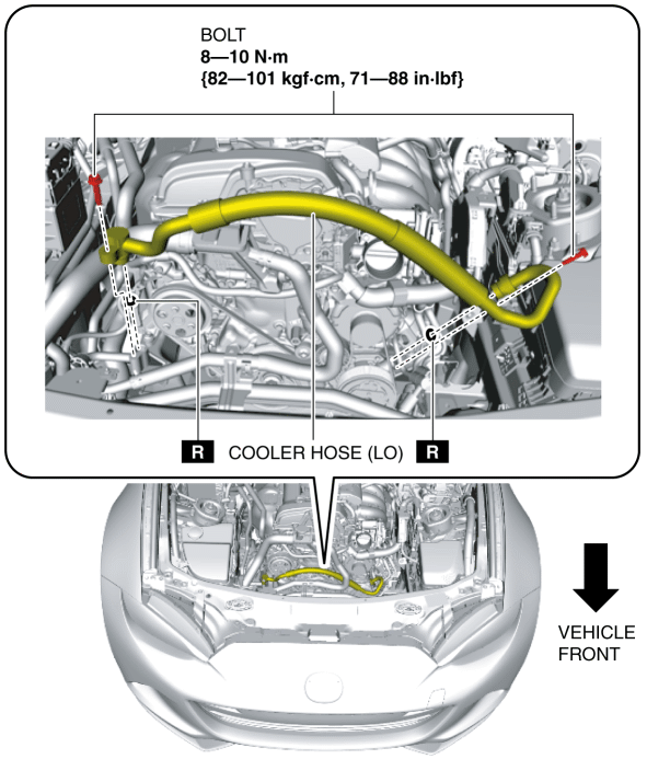
Cooler Hose (LO)
1. Disconnect the negative battery cable. (See NEGATIVE BATTERY CABLE DISCONNECTION/CONNECTION.)
2. Discharge the refrigerant from the system. (See REFRIGERANT RECOVERY.) (See REFRIGERANT CHARGING.)
3. Remove the following parts:a. Coolant reserve tank (See COOLANT RESERVE TANK REMOVAL/INSTALLATION [SKYACTIV-G 2.0].)b. Air cleaner, air hose and resonance chamber No.1 as a single unit (See INTAKE-AIR SYSTEM REMOVAL/INSTALLATION [SKYACTIV-G 2.0].)c. Battery and battery tray (See BATTERY REMOVAL/INSTALLATION [SKYACTIV-G 2.0].)
4. Remove the bolts. (See Refrigerant Line Removal Note.) (See Refrigerant Line Installation Note (1).)
CAUTION:
If moisture or foreign matter enters the refrigeration cycle, cooling ability will be lowered and abnormal noise will occur. Always immediately plug all open fittings after removing any refrigeration cycle parts to keep moisture or foreign matter out of the cycle.
5. Remove the cooler hose (LO). Do not allow compressor oil to spill.
6. Install in the reverse order of removal. (See Refrigerant Line Installation Note (2).)
7. Perform the refrigerant system performance test. (See REFRIGERANT SYSTEM PERFORMANCE TEST.)
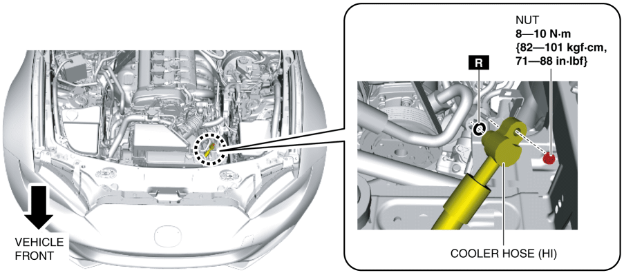
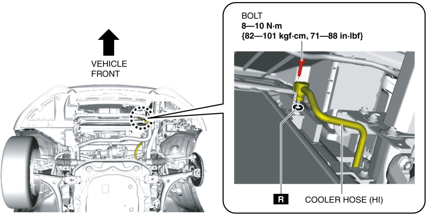
Cooler Hose (HI)
1. Disconnect the negative battery cable. (See NEGATIVE BATTERY CABLE DISCONNECTION/CONNECTION.)
2. Discharge the refrigerant from the system. (See REFRIGERANT RECOVERY.) (See REFRIGERANT CHARGING.)
3. Remove the following parts:a. Battery and battery tray (See BATTERY REMOVAL/INSTALLATION [SKYACTIV-G 2.0].)b. Front under cover (See FRONT UNDER COVER REMOVAL/INSTALLATION.)c. Front tire (LH) (See GENERAL PROCEDURES (SUSPENSION).)d. Front mudguard No.1 (LH) (See FRONT MUDGUARD REMOVAL/INSTALLATION.)e. Front splash shield No.2 (LH) (See FRONT SPLASH SHIELD No.2 REMOVAL/INSTALLATION.)
CAUTION:
If moisture or foreign matter enters the refrigeration cycle, cooling ability will be lowered and abnormal noise will occur. Always immediately plug all open fittings after removing any refrigeration cycle parts to keep moisture or foreign matter out of the cycle.
4. Remove the nut. (See Refrigerant Line Removal Note.) (See Refrigerant Line Installation Note (1).)
CAUTION:
If moisture or foreign matter enters the refrigeration cycle, cooling ability will be lowered and abnormal noise will occur. Always immediately plug all open fittings after removing any refrigeration cycle parts to keep moisture or foreign matter out of the cycle.
5. Remove the bolt. (See Refrigerant Line Removal Note.) (See Refrigerant Line Installation Note (1).)
6. Remove the seal plate (LH). (See SEAL PLATE REMOVAL/INSTALLATION.)
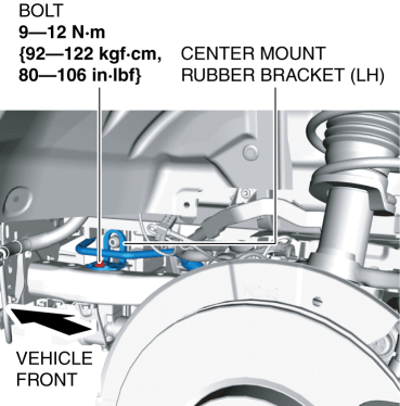
7. Remove the bolt.
8. Remove the center mount rubber bracket (LH).
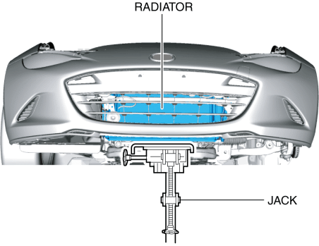
9. Support the radiator using a jack.
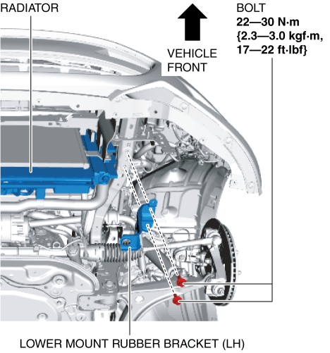
10. Remove the bolts.
11. Remove the lower mount rubber bracket (LH).
12. Remove the cooler hose (HI). Do not allow compressor oil to spill.
13. Install in the reverse order of removal. (See Refrigerant Line Installation Note (2).)
14. Perform the refrigerant system performance test. (See REFRIGERANT SYSTEM PERFORMANCE TEST.)
Cooler Pipe (LO)
1. Disconnect the negative battery cable. (See NEGATIVE BATTERY CABLE DISCONNECTION/CONNECTION.)
2. Discharge the refrigerant from the system. (See REFRIGERANT RECOVERY.) (See REFRIGERANT CHARGING.)
3. Remove the coolant reserve tank. (See COOLANT RESERVE TANK REMOVAL/INSTALLATION [SKYACTIV-G 2.0].)
4. Remove the air cleaner, air hose and resonance chamber No.1 as a single unit. (See INTAKE-AIR SYSTEM REMOVAL/INSTALLATION [SKYACTIV-G 2.0].)
CAUTION:
If moisture or foreign matter enters the refrigeration cycle, cooling ability will be lowered and abnormal noise will occur. Always immediately plug all open fittings after removing any refrigeration cycle parts to keep moisture or foreign matter out of the cycle.
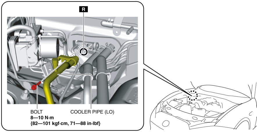
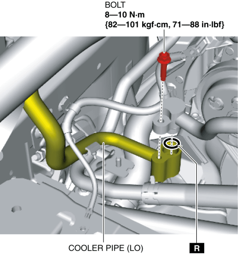
5. Remove the bolt. (See Refrigerant Line Removal Note.) (See Refrigerant Line Installation Note (1).)
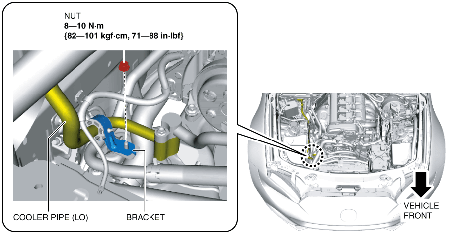
6. Remove the nut.
7. Remove the bracket.
CAUTION:
If moisture or foreign matter enters the refrigeration cycle, cooling ability will be lowered and abnormal noise will occur. Always immediately plug all open fittings after removing any refrigeration cycle parts to keep moisture or foreign matter out of the cycle.
8. Remove the bolt. (See Refrigerant Line Removal Note.) (See Refrigerant Line Installation Note (1).)
9. Remove the cooler pipe (LO). Do not allow compressor oil to spill.
10. Install in the reverse order of removal. (See Refrigerant Line Installation Note (2).)
11. Perform the refrigerant system performance test. (See REFRIGERANT SYSTEM PERFORMANCE TEST.)
Cooler Pipe (HI) A
1. Disconnect the negative battery cable. (See NEGATIVE BATTERY CABLE DISCONNECTION/CONNECTION.)
2. Discharge the refrigerant from the system. (See REFRIGERANT RECOVERY.) (See REFRIGERANT CHARGING.)
3. Remove the battery and battery tray. (See BATTERY REMOVAL/INSTALLATION [SKYACTIV-G 2.0].)
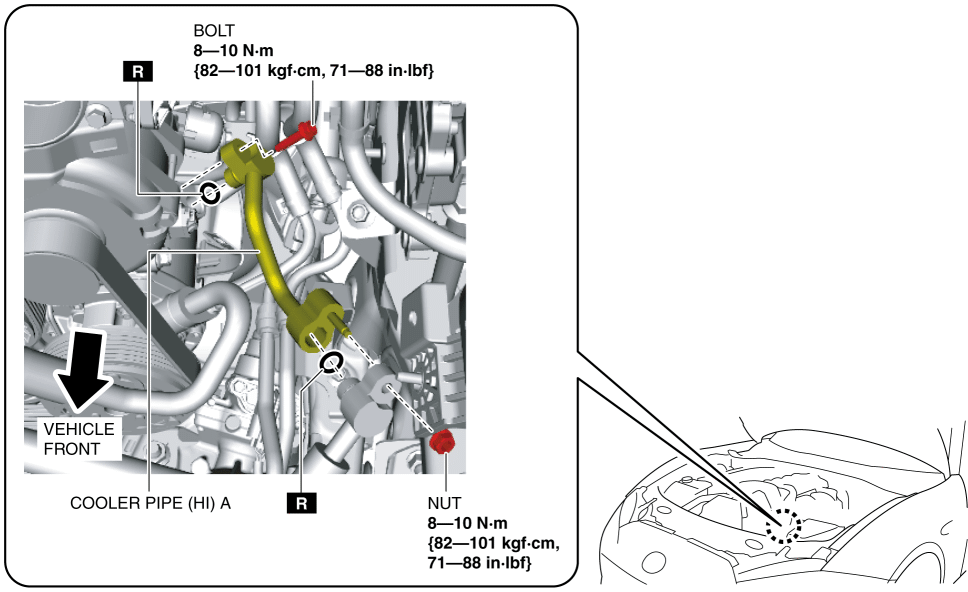
4. Remove the nut and bolt. (See Refrigerant Line Removal Note.) (See Refrigerant Line Installation Note (1).)
CAUTION:
If moisture or foreign matter enters the refrigeration cycle, cooling ability will be lowered and abnormal noise will occur. Always immediately plug all open fittings after removing any refrigeration cycle parts to keep moisture or foreign matter out of the cycle.
5. Remove the cooler pipe (HI) A. Do not allow compressor oil to spill.
6. Install in the reverse order of removal. (See Refrigerant Line Installation Note (2).)
7. Perform the refrigerant system performance test. (See REFRIGERANT SYSTEM PERFORMANCE TEST.)
Cooler Pipe (HI) B
1. Disconnect the negative battery cable. (See NEGATIVE BATTERY CABLE DISCONNECTION/CONNECTION.)
2. Discharge the refrigerant from the system. (See REFRIGERANT RECOVERY.) (See REFRIGERANT CHARGING.)
3. Remove the following parts:a. Coolant reserve tank (See COOLANT RESERVE TANK REMOVAL/INSTALLATION [SKYACTIV-G 2.0].)b. Air cleaner, air hose and resonance chamber No.1 as a single unit (See INTAKE-AIR SYSTEM REMOVAL/INSTALLATION [SKYACTIV-G 2.0].)c. Front under cover (See FRONT UNDER COVER REMOVAL/INSTALLATION.)d. Front tire (RH) (See GENERAL PROCEDURES (SUSPENSION).)e. Front mudguard No.1 (RH) (See FRONT MUDGUARD REMOVAL/INSTALLATION.)f. Front splash shield No.2 (RH) (See FRONT SPLASH SHIELD No.2 REMOVAL/INSTALLATION.)
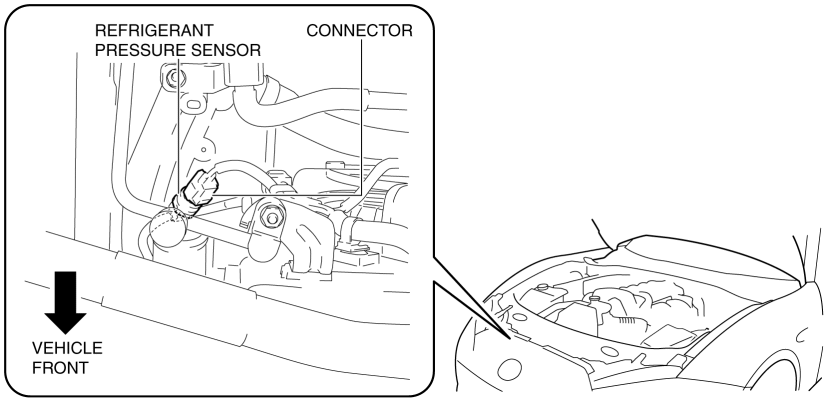
4. Disconnect the connector.
CAUTION:
If moisture or foreign matter enters the refrigeration cycle, cooling ability will be lowered and abnormal noise will occur. Always immediately plug all open fittings after removing any refrigeration cycle parts to keep moisture or foreign matter out of the cycle.
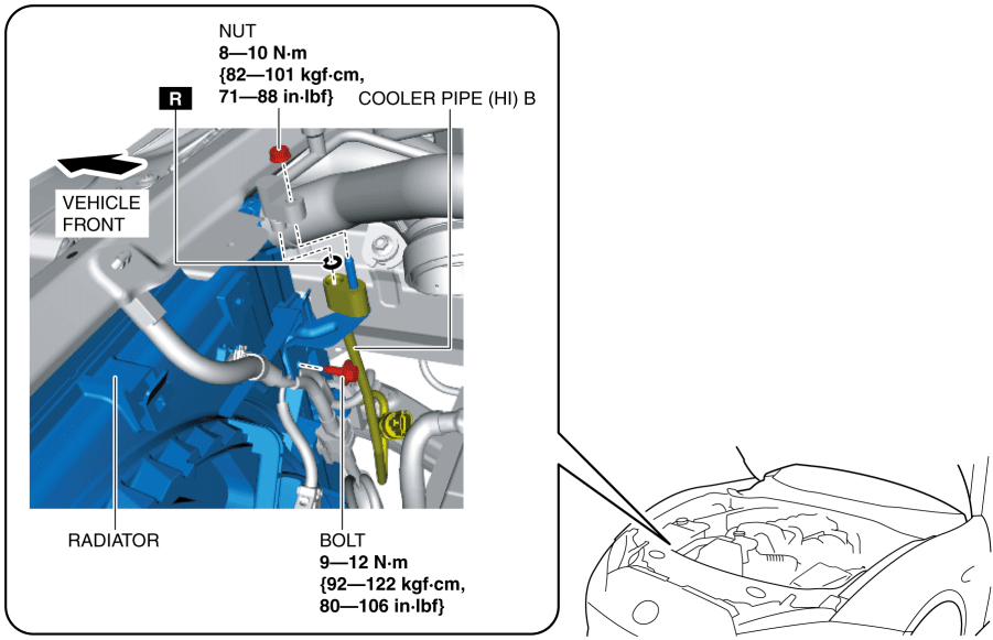
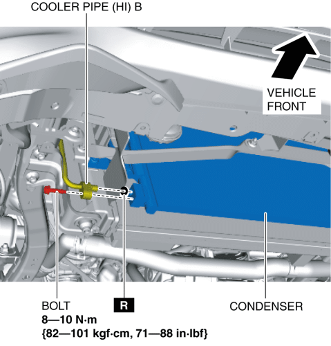
5. Remove the nut and bolt. (See Refrigerant Line Removal Note.) (See Refrigerant Line Installation Note (1).)
CAUTION:
If moisture or foreign matter enters the refrigeration cycle, cooling ability will be lowered and abnormal noise will occur. Always immediately plug all open fittings after removing any refrigeration cycle parts to keep moisture or foreign matter out of the cycle.
6. Remove the bolt. (See Refrigerant Line Removal Note.) (See Refrigerant Line Installation Note (1).)
7. Remove the seal plate (RH). (See SEAL PLATE REMOVAL/INSTALLATION.)
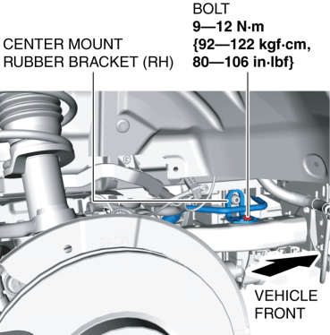
8. Remove the bolt.
9. Remove the center mount rubber bracket (RH).
10. Support the radiator using a jack.
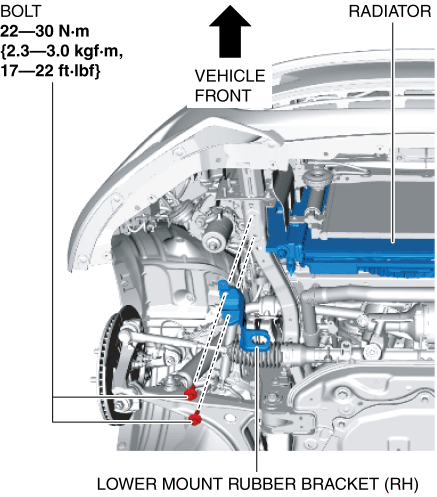
11. Remove the bolts.
12. Remove the lower mount rubber bracket (RH).
13. Remove the cooler pipe (HI) B. Do not allow compressor oil to spill.
14. Install in the reverse order of removal. (See Refrigerant Line Installation Note (2).)
15. Perform the refrigerant system performance test. (See REFRIGERANT SYSTEM PERFORMANCE TEST.)
Cooler Pipe (HI) C
1. Disconnect the negative battery cable. (See NEGATIVE BATTERY CABLE DISCONNECTION/CONNECTION.)
2. Discharge the refrigerant from the system. (See REFRIGERANT RECOVERY.) (See REFRIGERANT CHARGING.)
3. Remove the following parts:a. Coolant reserve tank (See COOLANT RESERVE TANK REMOVAL/INSTALLATION [SKYACTIV-G 2.0].)b. Air cleaner, air hose and resonance chamber No.1 as a single unit (See INTAKE-AIR SYSTEM REMOVAL/INSTALLATION [SKYACTIV-G 2.0].)c. EVP control unit (See EVP CONTROL UNIT REMOVAL/INSTALLATION.)
CAUTION:
If moisture or foreign matter enters the refrigeration cycle, cooling ability will be lowered and abnormal noise will occur. Always immediately plug all open fittings after removing any refrigeration cycle parts to keep moisture or foreign matter out of the cycle.
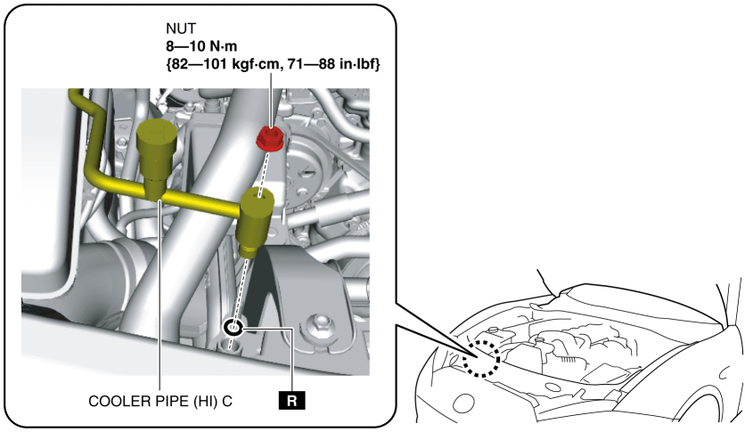
4. Remove the bolt. (See Refrigerant Line Removal Note.) (See Refrigerant Line Installation Note (1).)
CAUTION:
If moisture or foreign matter enters the refrigeration cycle, cooling ability will be lowered and abnormal noise will occur. Always immediately plug all open fittings after removing any refrigeration cycle parts to keep moisture or foreign matter out of the cycle.
5. Remove the nut. (See Refrigerant Line Removal Note.) (See Refrigerant Line Installation Note (1).)
6. Remove the cooler pipe (HI) C. Do not allow compressor oil to spill.
7. Install in the reverse order of removal. (See Refrigerant Line Installation Note (2).)
8. Perform the refrigerant system performance test. (See REFRIGERANT SYSTEM PERFORMANCE TEST.)
Refrigerant Line Removal Note
CAUTION:
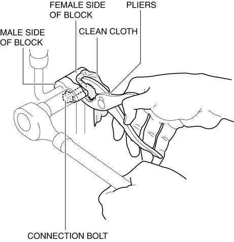
When securing the block with pliers, wrap a clean cloth around the block. If the block is secured with pliers directly, it could be damaged.
1. Disconnect the block joint type pipes by grasping the female side of the block with pliers or similar tool and holding firmly, then tighten the connection bolt or nut.
Refrigerant Line Installation Note (1)
1. Apply compressor oil to the O-rings and connect the joints.
2. Tighten the joint bolt or nut by hand.
CAUTION:
When securing the block with pliers, wrap a clean cloth around the block. If the block is secured with pliers directly, it could be damaged.
3. Connect the block joint type pipes by grasping the female side of the block with pliers or similar tool and holding firmly, then tighten the connection bolt or nut.
Refrigerant Line Installation Note (2)
1. After replacing the refrigerant line, add compressor oil to the refrigeration cycle.< Previous Next >
Replaced refrigerant line
Supplemental compressor oil amount (approx. quantity)
Cooler hose (LO)
1 ml {1 cc, 0.03 US fl oz}
Cooler hose (HI)
3 ml {3 cc, 0.1 US fl oz}
Cooler pipe (LO)
1 ml {1 cc, 0.03 US fl oz}
Cooler pipe (HI) A
1 ml {1 cc, 0.03 US fl oz}
Cooler pipe (HI) B
1 ml {1 cc, 0.03 US fl oz}
Cooler pipe (HI) C
1 ml {1 cc, 0.03 US fl oz}
