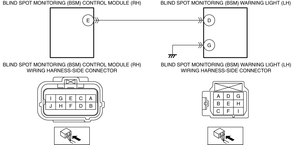
DTC B11D3:11 [BLIND SPOT MONITORING (BSM) CONTROL MODULE]
CAUTION:
When replacing a blind spot monitoring (BSM) control module (RH) having any of the following part numbers, it is necessary to replace the blind spot monitoring (BSM) control module (LH) at the same time to perform the configuration normally.
N243-67Y80 A
N243-67Y80 B
N243-67Y80 C
| Description |
Blind spot monitoring (BSM) warning light (LH) circuit malfunction |
| Detection condition |
|
| Fail-safe |
|
| Possible cause |
|
| Step |
Inspection |
Action |
|
| 1 |
INSPECT BLIND SPOT MONITORING (BSM) WARNING LIGHT (LH) CONNECTOR CONDITION
|
Yes |
Go to the next step. |
| No |
Repair or replace the connector, then go to Step 5. |
||
| 2 |
INSPECT BLIND SPOT MONITORING (BSM) CONTROL MODULE (RH) CONNECTOR CONDITION
|
Yes |
Go to the next step. |
| No |
Repair or replace the connector, then go to Step 5. |
||
| 3 |
INSPECT BLIND SPOT MONITORING (BSM) WARNING LIGHT (LH) CIRCUIT FOR SHORT TO GROUND
|
Yes |
Refer to the wiring diagram and verify whether or not there is a common connector between blind spot monitoring (BSM) control module (RH) terminal E and blind spot monitoring (BSM) warning light (LH) terminal D.
Go to Step 5. |
| No |
Go to the next step. |
||
| 4 |
INSPECT BLIND SPOT MONITORING (BSM) WARNING LIGHT (LH)
|
Yes |
Go to the next step. |
| No |
Replace the outer mirror glass (LH), then go to the next step. (See OUTER MIRROR GLASS REMOVAL.) |
||
| 5 |
VERIFY THAT REPAIRS HAVE BEEN COMPLETED
|
Yes |
Repeat the inspection from Step 1.
Go to the next step. |
| No |
Go to the next step. |
||
| 6 |
VERIFY IF OTHER DTCs DISPLAYED
|
Yes |
Repair or replace the malfunctioning part according to the applicable DTC troubleshooting. (See DTC TABLE [BLIND SPOT MONITORING (BSM) CONTROL MODULE].) |
| No |
DTC troubleshooting completed. |
||
