< Previous
Next >
ANTENNA FEEDER NO.2 INSPECTION
Without Center Display
1. Disconnect the negative battery cable. (See NEGATIVE BATTERY CABLE DISCONNECTION/CONNECTION.)
2. Remove the scuff plate (passenger's side). (See SCUFF PLATE REMOVAL/INSTALLATION.)
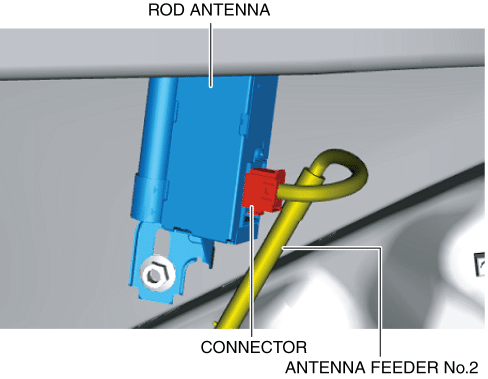
3. Disconnect the connector.
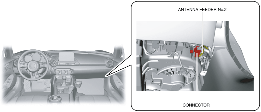
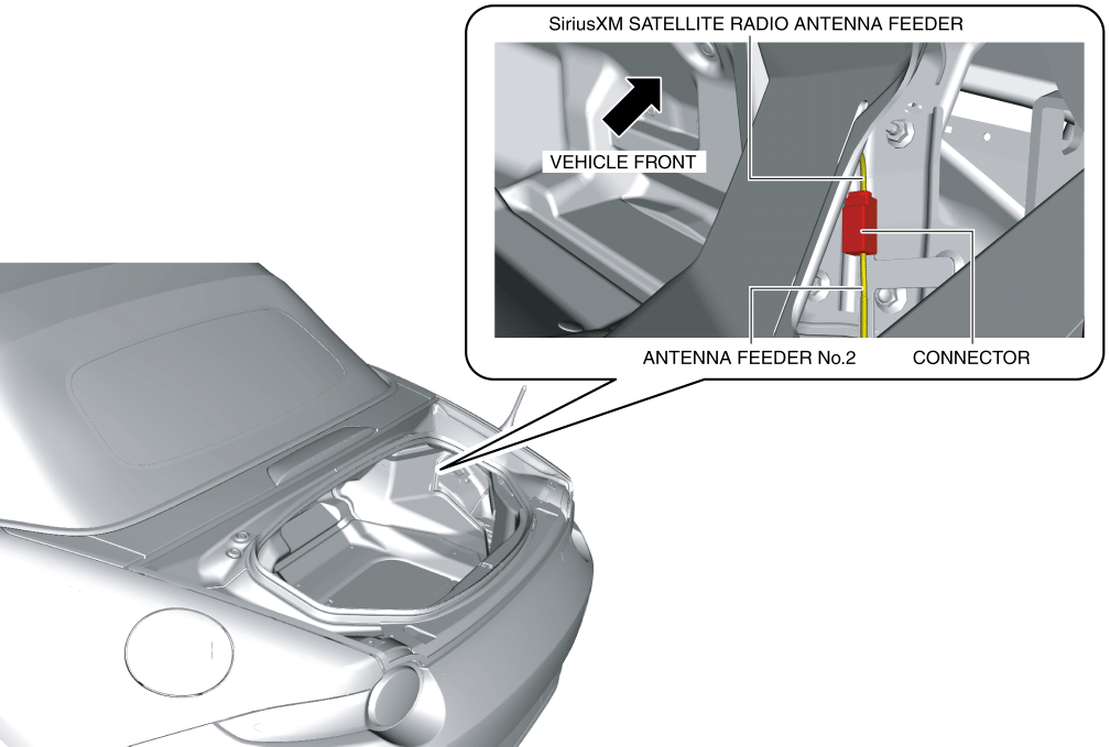
4. Remove the service hole cover on the trunk side trim (RH).

5. Disconnect the connector.
6. Verify that the continuity between antenna feeder No.2 terminals is as indicated in the table.
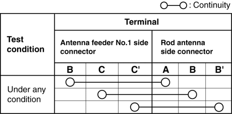
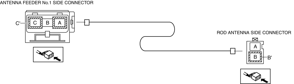
If not as indicated in the table, replace the antenna feeder No.2. (See ANTENNA FEEDER NO.2 REMOVAL/INSTALLATION.)
With Center Display
1. Disconnect the negative battery cable. (See NEGATIVE BATTERY CABLE DISCONNECTION/CONNECTION.)
2. Remove the following parts:a. Scuff plate (passenger's side) (See SCUFF PLATE REMOVAL/INSTALLATION.)b. Front side trim (passenger's side) (See FRONT SIDE TRIM REMOVAL/INSTALLATION.)c. A-pillar trim (passenger's side) (See A-PILLAR TRIM REMOVAL/INSTALLATION.)d. Passenger-side lower panel (See PASSENGER-SIDE LOWER PANEL REMOVAL/INSTALLATION.)e. LF control unit (with advanced keyless entry system) (See LF CONTROL UNIT REMOVAL/INSTALLATION.)f. LF control unit bracket (with advanced keyless entry system) (See LF CONTROL UNIT REMOVAL/INSTALLATION.)
3. Disconnect the connectors.
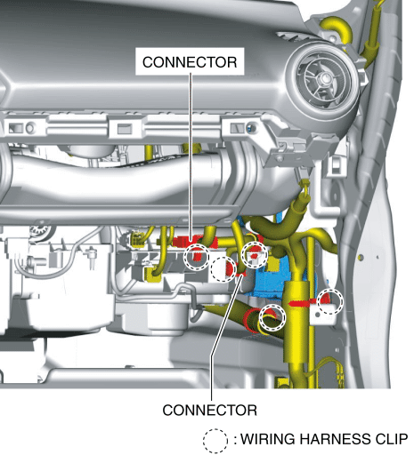
4. Pull out the wiring harness clips.
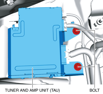
5. Remove the bolts.
6. Move the tuner and amp unit (TAU) in the direction of arrow (1) shown in the figure and detach the guide from the body.
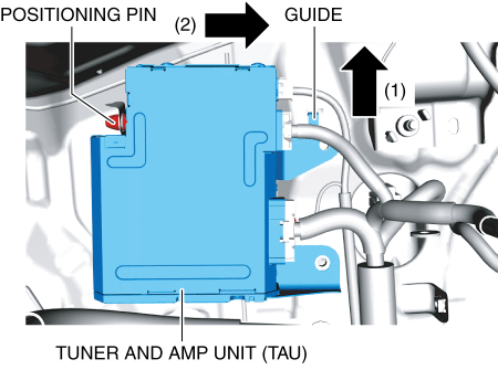
7. Move the tuner and amp unit (TAU) in the direction of arrow (2) shown in the figure and detach the positioning pin from the body.
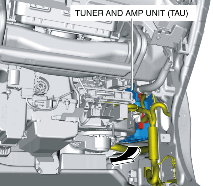
8. Pull out the tuner and amp unit (TAU) to the position where the connector can be pulled out in the direction of the arrow.
9. Disconnect the connectors.
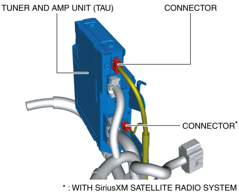
10. Remove the service hole cover on the trunk side trim (RH).
11. Disconnect the connector.
12. Disconnect the connector. (With SiriusXM satellite radio system)
13. Verify that the continuity between antenna feeder No.2 terminals is as indicated in the table.< Previous Next >
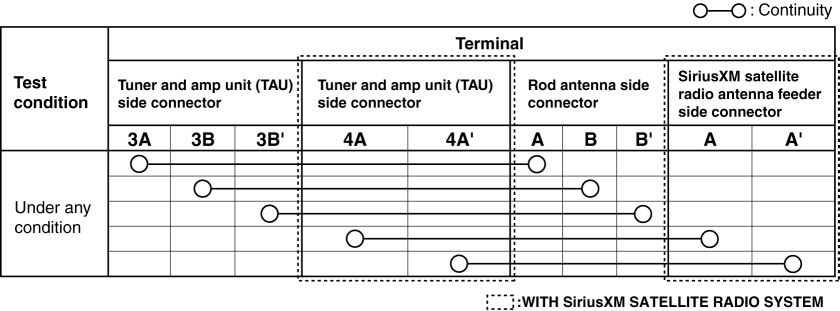
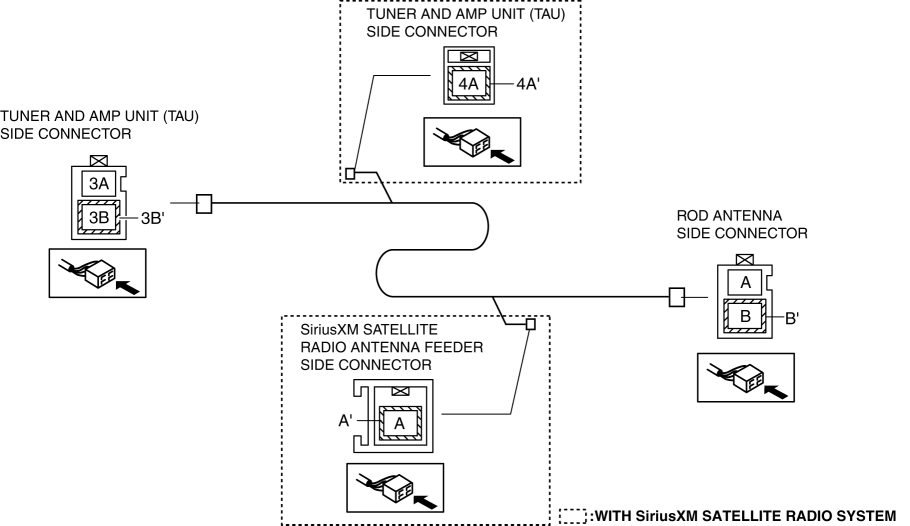
If not as indicated in the table, replace the antenna feeder No.2. (See ANTENNA FEEDER NO.2 REMOVAL/INSTALLATION.)