NO.3 WILL NOT CRANK [SKYACTIV-G 2.0]
| 3 |
WILL NOT CRANK |
| DESCRIPTION |
|
| POSSIBLE CAUSE |
WARNING:
CAUTION:
|
| |
|
CAUTION:
Related PIDs
Verify the malfunction symptom according to not only the PID value but also the symptom troubleshooting.
| Item (definition) |
Unit/Condition |
Definition |
Condition/Specification (Reference) |
| VPWR |
V |
Battery positive voltage |
|
| STEP |
INSPECTION |
RESULTS |
ACTION |
| 1 |
DETERMINE IF MALFUNCTION CAUSE IS IMMOBILIZER SYSTEM OR OTHER
|
Yes |
Both conditions present:
|
| No |
Either or other condition present:
|
||
| 2 |
INSPECT PUSH BUTTON START CONNECTOR CONNECTION
|
Yes |
Go to the next step. |
| No |
Reconnect the push button start securely, then repeat from Step 1. |
||
| 3 |
DETERMINE IF MALFUNCTION CAUSE IS INSTRUMENT CLUSTER OR OTHER
|
Yes |
Go to the next step. |
| No |
Inspect the following wiring harness and connectors:
Inspect the instrument cluster. (See INSTRUMENT CLUSTER INSPECTION.)
|
||
| 4 |
VERIFY IMMOBILIZER SYSTEM DTC
|
Yes |
Go to the applicable DTC inspection. (See DTC TABLE [START STOP UNIT].) |
| No |
Go to the next step. |
||
| 5 |
VERIFY PCM DTC
|
Yes |
Continuous memory DTC is displayed:
Communication error message is displayed:
|
| No |
Go to the next step. |
||
| 6 |
INSPECT POWER SUPPLY
|
Yes |
Go to the next step. |
| No |
Inspect the following:
|
||
| 7 |
DETERMINE IF MALFUNCTION CAUSE IS STARTER RELAY CONTROL SIGNAL CIRCUIT OR OTHER
|
Yes |
Go to Step 21. |
| No |
AT:
MT:
|
||
| 8 |
DETERMINE IF MALFUNCTION CAUSE IS STARTER INTERLOCK SWITCH OR OTHER
|
Yes |
Inspect the starter interlock switch. (See STARTER INTERLOCK SWITCH INSPECTION [SKYACTIV-G 2.0].)
|
| No |
Go to the next step. |
||
| 9 |
INSPECT STARTER INTERLOCK SWITCH CONNECTOR CONDITION
|
Yes |
Repair or replace the connector and/or terminals, then repeat Step 7. |
| No |
Go to the next step. |
||
| 10 |
INSPECT STARTER INTERLOCK SWITCH GROUND CIRCUIT FOR OPEN CIRCUIT
|
Yes |
Go to Step 14. |
| No |
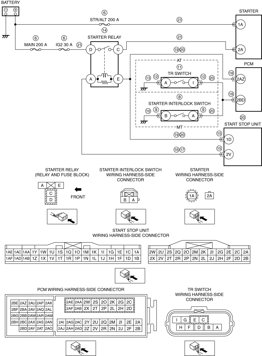
Refer to the wiring diagram and verify whether or not there is a common connector between starter interlock switch terminal B and body ground.
Repeat Step 7. |
||
| 11 |
DETERMINE IF MALFUNCTION CAUSE IS TR SWITCH OR OTHER
|
Yes |
Inspect the TR switch. (See TRANSMISSION RANGE (TR) SWITCH INSPECTION [SJ6A-EL].)
|
| No |
Go to the next step. |
||
| 12 |
INSPECT TR SWITCH CONNECTOR CONDITION
|
Yes |
Repair or replace the connector and/or terminals, then repeat Step 7. |
| No |
Go to the next step. |
||
| 13 |
INSPECT TR SWITCH GROUND CIRCUIT FOR OPEN CIRCUIT
|
Yes |
Go to the next step. |
| No |
Refer to the wiring diagram and verify whether or not there is a common connector between TR switch terminal A and body ground.
Repeat Step 7. |
||
| 14 |
INSPECT STARTER RELAY
|
Yes |
Replace the starter relay. Repeat Step 7. |
| No |
Go to the next step. |
||
| 15 |
INSPECT START STOP UNIT CONNECTOR CONDITION
|
Yes |
Repair or replace the connector and/or terminals, then repeat Step 7. |
| No |
Go to the next step. |
||
| 16 |
INSPECT STARTER RELAY CONTROL CIRCUIT FOR SHORT TO GROUND
|
Yes |
Refer to the wiring diagram and verify whether or not there is a common connector between starter relay terminal A and start stop unit terminal 2V.
Repeat Step 7. |
| No |
Go to the next step. |
||
| 17 |
INSPECT STARTER RELAY CONTROL CIRCUIT FOR OPEN CIRCUIT
|
Yes |
Go to the next step. |
| No |
Refer to the wiring diagram and verify whether or not there is a common connector between starter relay terminal A and start stop unit terminal 2V.
Repeat Step 7. |
||
| 18 |
INSPECT PCM CONNECTOR CONDITION
|
Yes |
Repair or replace the connector and/or terminals, then repeat Step 7. |
| No |
Go to the next step. |
||
| 19 |
INSPECT STARTER RELAY CONTROL CIRCUIT FOR SHORT TO GROUND
|
Yes |
Refer to the wiring diagram and verify whether or not there is a common connector between the following terminals:
Repeat Step 7. |
| No |
Go to the next step. |
||
| 20 |
INSPECT STARTER RELAY CONTROL CIRCUIT FOR OPEN CIRCUIT
|
Yes |
Inspect the start stop unit. (See START STOP UNIT INSPECTION.)
|
| No |
Refer to the wiring diagram and verify whether or not there is a common connector between the following terminals:
Repeat Step 7. |
||
| 21 |
INSPECT WIRING HARNESS OF STARTER POWER SUPPLY CIRCUIT
|
Yes |
Repair or replace the suspected wiring harness. |
| No |
Go to the next step. |
||
| 22 |
INSPECT STARTING SYSTEM
|
Yes |
Repair or replace the malfunctioning part according to the inspection results. |
| No |
Go to the next step. |
||
| 23 |
INSPECT IMMOBILIZER SYSTEM RELATED CIRCUIT
|
Yes |
Repair or replace the malfunctioning part according to the inspection results. |
| No |
Go to the next step. |
||
| 24 |
VERIFY PRESENT MALFUNCTION DTC
|
Yes |
Go to the applicable DTC inspection. |
| No |
Go to the next step. |
||
| 25 |
DETERMINE IF MALFUNCTION CAUSE IS BASE ENGINE OR OTHER
|
Yes |
Repair or replace the malfunctioning part according to the inspection results. |
| No |
Base engine malfunction or engine damage during compression due to liquid (such as water, fuel, or engine oil) penetration into cylinder.
|
||
| 26 |
Verify the test results.
|
||