EVAPORATIVE EMISSION (EVAP) CONTROL SYSTEM [SKYACTIV-G 2.0]
Outline
The evaporative emission control system prevents release of evaporative gas into the atmosphere.
Evaporative gas is introduced into the intake manifold by the intake manifold vacuum, mixed with intake air, and then combusted.
System Diagram
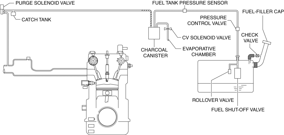
U.S.A. and CANADA specs.
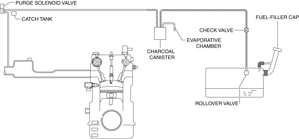
Except U.S.A. and CANADA specs.
Structure
U.S.A. and CANADA specs.
The evaporative emission control system consists of the following parts:
| Part name |
Reference |
| Purge solenoid valve |
|
| Catch tank |
(See CATCH TANK [SKYACTIV-G 2.0].) |
| Fuel tank pressure sensor |
|
| Charcoal canister |
|
| Evaporative chamber |
|
| Fuel-filler cap |
|
| Rollover valve |
|
| Check valve |
(See CHECK VALVE [SKYACTIV-G 2.0].) |
| Fuel shut-off valve |
|
| CV solenoid valve |
|
| Pressure control valve |
| Part name |
Reference |
| Purge solenoid valve |
|
| Catch tank |
(See CATCH TANK [SKYACTIV-G 2.0].) |
| Charcoal canister |
|
| Evaporative chamber |
|
| Fuel-filler cap |
|
| Rollover valve |
|
| Check valve |
(See CHECK VALVE [SKYACTIV-G 2.0].) |

